
How TBM Electrical Systems Distribute Power and Protect Against Faults
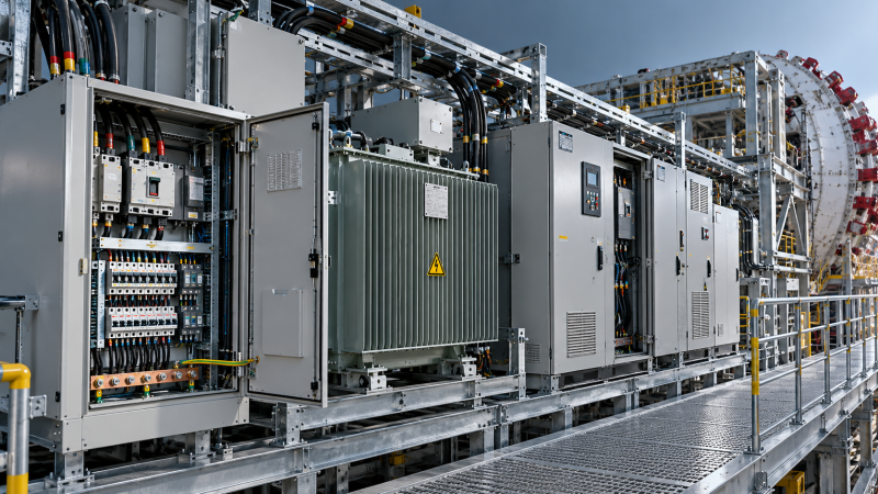
A tunnel boring machine distributes electrical power through several stages: an incoming supply feeds switchgear and transformers, which supply motor drives, auxiliary machinery, and control circuits. Fault protection must work across that entire chain. A downstream fault should be cleared before it damages cables or equipment, while healthy circuits remain available wherever continued operation is safe.
For technical evaluators, the decisive questions are whether the network can support the required operating loads and whether its protective devices respond correctly under the actual tunnel supply conditions. Installed power alone answers neither question. Cable length, source impedance, grounding arrangements, drive behavior, and the division between essential and nonessential loads all influence how reliably a TBM can excavate—and how safely it stops when something goes wrong.
Follow the power path from the tunnel supply to each load
On a large TBM, power may arrive through a medium-voltage trailing cable connected to the project’s tunnel distribution network. Incoming switchgear provides switching, isolation, and protection before power reaches transformers on the machine or its backup system. These transformers establish the voltage levels needed by propulsion equipment, process machinery, and auxiliary services. Smaller machines and different project arrangements may use another supply architecture, so the project single-line diagram must establish the actual boundaries.
The main loads can include cutterhead drives, hydraulic power units, slurry pumps, screw conveyors, belt conveyors, ventilation equipment, cooling systems, and dewatering pumps. Their electrical behavior differs substantially. A cutterhead drive must respond to changing torque demand; a pump may run for extended periods; a conveyor may need a controlled start while carrying material. Adding their nameplate ratings gives an incomplete picture of supply demand.
Variable-frequency drives regulate motor speed and torque by converting incoming AC power through an electronic power stage. They can reduce starting current compared with direct-on-line starting and support controlled acceleration. They also introduce requirements for harmonic assessment, electromagnetic compatibility, cooling, and protection suitable for power electronics. Their presence changes the network study; it does not remove the need for one.
Auxiliary distribution supplies lighting, outlets, instrumentation, communications, and control equipment through dedicated circuits and, where required, additional transformers or power supplies. Separating these circuits helps prevent a fault in a minor service from disabling a major operating function. However, physical separation of panels is insufficient if they still depend on one upstream protective device or a common control power supply.
The single-line diagram should make these dependencies visible. It should identify transformer ratings and impedances, switching devices, protective functions, grounding arrangements, cable sections, and essential supply paths. The evaluator should be able to trace both the normal route of power and what remains energized after each major breaker opens.
Check the supply at the machine’s operating limits
A distribution design that works near the tunnel entrance may behave differently after the TBM has advanced. Longer supply cables add impedance, increasing voltage drop and reducing available fault current at the machine. Cable extensions and changes to the project supply can therefore affect both excavation performance and protection sensitivity.
The assessment should cover credible combinations of loads, including excavation, conveyor acceleration, pumping, and restarting after an interruption. During a supply disturbance, simultaneous restart of several auxiliaries can produce another voltage dip and repeated trips. A staged restart sequence can limit this effect, provided it preserves the process functions needed for a safe recovery.
Cable selection also requires more than an ampacity calculation. Installation conditions, grouping, ambient temperature, mechanical protection, permissible bending, and reel configuration affect suitability. A cable wound on a reel may have a different thermal limit from the same cable fully deployed. At the other end of the distribution chain, motor cable length must be checked against the drive manufacturer’s limits because inverter switching can create damaging voltage stress at motor terminals.
Coordinate protection around the faults the network can actually produce
TBM equipment electrical systems must distinguish sustained overloads, short circuits, earth faults, and abnormal supply conditions. These events develop differently and require different responses. An overloaded motor may need a controlled stop before its thermal limit is exceeded; a high-current short circuit requires rapid interruption; a developing insulation fault may justify an alarm or disconnection depending on the grounding system and applicable requirements.
Protection coordination determines which device operates first and whether upstream devices remain closed. For example, a fault on a cooling-pump feeder should normally be cleared by that feeder’s protection. If the incoming breaker operates first, the machine may lose multiple process functions even though the original fault was confined to one branch.
Selective operation has practical limits. Achieving a delay between upstream and downstream devices can expose equipment to more fault energy. At some fault levels, the required separation may exceed cable thermal withstand or equipment ratings. A coordination study must therefore balance selectivity, clearing time, equipment withstand, and personnel protection instead of assuming that every fault can be isolated without wider interruption.
- Maximum prospective fault current establishes the required interrupting capacity and short-circuit withstand of switchgear and related equipment.
- Minimum prospective fault current establishes whether protection can detect and clear faults at electrically remote locations.
- Cable and transformer withstand limits how much fault energy can pass before damage becomes unacceptable.
- Motor and drive characteristics determine which overload, temperature, phase-loss, and electronic protection functions are required.
Both maximum and minimum fault conditions matter. A stronger supply can exceed a breaker’s interrupting rating, while a long cable connected to a weaker supply may limit fault current enough to delay an instantaneous overcurrent element. Checking only the maximum fault level leaves the second problem unresolved.
Drive-fed motors need particular attention. A variable-frequency drive limits and controls its output current, so its response to an output fault differs from a motor connected directly to the supply. The drive’s electronic functions, upstream fuses or breakers, motor thermal protection, and cable protection must follow a compatible design. An upstream breaker cannot automatically be assumed to provide every protection function downstream of the inverter.
Arc-flash exposure also depends on clearing time and equipment configuration, not simply on system voltage. Coordination choices that increase delay can increase incident energy. Where arc-flash assessment is required, it should use the proposed protection settings and relevant operating configurations. Remote switching, suitable enclosure design, and maintenance arrangements can then be evaluated against the identified exposure.
Grounding and monitoring determine how earth faults are handled
The grounding arrangement establishes the path that fault current takes and strongly influences detection. Solidly grounded, resistance-grounded, and unearthed or impedance-earthed systems behave differently. Their protection methods cannot be exchanged without reconsidering touch voltage, fault current, insulation stress, and disconnection requirements.
In a suitably designed IT system, a first insulation fault may generate an alarm while operation continues under defined conditions. That approach requires insulation monitoring, a means of locating the fault, and an effective response procedure. A second fault on another live conductor can create a much more severe condition. Continued operation after the first alarm is therefore a managed operating state with clear limits.
Resistance grounding limits earth-fault current through a deliberate impedance. Its effectiveness depends on selecting that impedance for the network and coordinating detection with the resulting current. Network capacitance, connected equipment, and possible changes to the supply arrangement need consideration. An earth-fault relay setting copied from a different installation may be unsuitable.
Protective bonding connects exposed conductive parts so that a fault does not create an uncontrolled voltage difference between accessible structures. On a TBM, the bonding design must account for articulated sections, backup gantries, cable supports, and mechanically assembled equipment. Structural contact through bolted or moving interfaces should not be assumed to provide a dependable protective path without verification.
Wet conditions, conductive contamination, vibration, and cable movement make insulation condition and connection integrity important maintenance indicators. Monitoring can reveal a deteriorating condition before it becomes a trip, but the signal needs context. A changing insulation reading may relate to moisture ingress, damaged cabling, connected filters, or a particular operating configuration. Fault-location capability and clear alarm records make that information actionable.
Residual-current protection also requires careful application around electronic drives. Leakage currents and non-sinusoidal residual currents can affect device selection and behavior. Where such protection is required, its type, sensitivity, and coordination should match the connected equipment and governing rules. Excessively sensitive protection applied without this assessment can cause unwanted trips, while an unsuitable device may fail to provide the intended protection.
Define a safe response before accepting the protection design
Electrical isolation and process safety must be considered together. Loss of excavation power does not necessarily remove the need for drainage, communications, monitoring, emergency lighting, or selected ventilation functions. Conversely, keeping a circuit energized is acceptable only when doing so remains safe under the fault condition. Essential-load designation needs a hazard-based justification and a defined supply arrangement.
A useful design review follows several fault scenarios through to their operational consequences: an earth fault on a motor feeder, loss of an incoming phase, failure of a control power supply, a drive cooling fault, and loss of the main tunnel supply. For each event, the documentation should show what detects it, what trips, what remains available, and what conditions permit restart. This exposes shared dependencies that a component list can conceal.
Emergency stopping requires the same attention. Removing torque from a drive does not electrically isolate its terminals, and stored energy may remain in DC links or other equipment after switching. The required stopping behavior, isolation points, discharge provisions, and verification of absence of voltage must be addressed separately. Maintenance access should support a defined isolation procedure that accounts for alternative supplies and possible backfeeds.
Standards provide a framework, but their applicability must be mapped to the actual installation. IEC 60204-1 addresses electrical equipment of machinery, while IEC 60204-11 covers machinery electrical equipment operating at higher supply voltages within its scope. EN 16191 addresses safety requirements for tunnelling machinery. Applicable editions, national adoption, project specifications, and the boundary between tunnel infrastructure and machine equipment determine how these documents are used. A declaration listing standards does not demonstrate that the project’s supply and protection interfaces have been resolved.
Acceptance should combine document review with checks of the installed system. Relevant evidence includes the load assessment, short-circuit and coordination studies, grounding design, cable calculations, protection settings, and functional test records. Protective-conductor continuity, insulation condition, relay operation, interlocks, emergency functions, and restart behavior should be verified using procedures appropriate to the equipment. Insulation testing must account for sensitive electronics and manufacturer instructions.
After commissioning, cable extensions, transformer substitutions, revised relay settings, and added loads can invalidate earlier assumptions. Those changes should trigger review of the affected calculations and functions. The most useful acceptance question is concrete: at the machine’s furthest planned supply point, under the weakest credible source condition, will a fault be detected and cleared in time—and will the remaining electrical services support the required safe state?
Related News
 Oct 26, 2026How TBM Electrical Systems Distribute Power and Protect Against FaultsExplore how TBM equipment electrical systems distribute power, coordinate fault protection, and maintain essential services. Learn what to check for safer, more reliable tunneling.
 Oct 25, 2026Comparing Industrial Equipment Suppliers: Lead Times, Warranties, and ServiceMake a smarter industrial equipment supplier comparison. Explore lead times, warranty coverage, and service support to reduce downtime risk and choose with confidence.
 Oct 24, 2026Choosing Lifting Equipment for Middle East Petrochemical Plants in Hazardous AreasExplore petrochemical lifting equipment Middle East plants can rely on. Compare hazardous-area certification, capacity, and heat limits to make informed procurement decisions.
 Oct 23, 2026Selecting Lifting Equipment for Nuclear Component Transport: Key Safety CriteriaSelecting lifting machinery for nuclear component transport? Discover essential safety criteria, load control checks, and supplier requirements to guide confident procurement.


Related News

Ms. Elena Rodriguez
Weekly Insights
Stay ahead with our curated technology reports delivered every Monday.