
Selecting Lifting Equipment for Nuclear Component Transport: Key Safety Criteria

Selecting lifting machinery for nuclear component transport starts with two questions: can the equipment control the load throughout the planned movement, and what would happen if that control were lost? Rated capacity is only one part of the answer. A suitable system must also protect the component, remain stable along the route, and meet the safety requirements assigned to that particular lift.
A reactor vessel section arriving at a construction site, a replacement heat exchanger entering an operating facility, and a transport package containing radioactive material present different constraints. Equipment selection should follow the load, route, and consequences of failure. Choosing a crane first and adapting the lift around it can leave significant risks unresolved.
Define the lift’s safety requirements before comparing equipment
A component’s connection to a nuclear project does not automatically determine the lifting equipment it needs. The selection basis depends on the facility’s requirements, the component’s condition, and the potential effects of a dropped or uncontrolled load.
For an uninstalled component at a construction site, the principal concerns may include personnel safety, structural damage, and component integrity. Inside an operating facility, the same movement could also threaten equipment needed for safe operation. Where radioactive contents are involved, package integrity and radiological controls introduce further constraints.
The lift specification should therefore establish:
- The component’s condition, including whether it is clean, contaminated, activated, or contains radioactive material.
- The structures, systems, personnel areas, and other loads exposed along the route.
- The applicable legal, facility, contractual, and engineering requirements.
- Whether failure prevention, physical protection, route restrictions, or a combination of measures is required.
- The review and authorization needed before equipment is accepted and lifting begins.
Terms such as “critical lift,” “nuclear grade,” and “single-failure-proof” need a defined technical meaning in the procurement documents. A supplier’s label alone does not establish suitability. Where single-failure protection is required, the evidence must address the specified load path and credible failures, rather than simply identify duplicate components.
Build a load description that includes more than weight
The equipment supplier needs a controlled load description: component mass, dimensions, center of gravity, approved lifting points, allowable orientation, and restrictions on acceleration, deformation, or contact. Include preservation frames, temporary attachments, retained contents, and transport fixtures where applicable.
Distinguish the component weight from the total load imposed on the crane. Depending on the manufacturer’s load-chart conventions, deductions may be needed for hook blocks, slings, spreader beams, and other lifting accessories. Every comparison should use the same weight basis.
Uncertainty in the center of gravity can be as important as uncertainty in weight. An offset center of gravity changes sling forces, lifting-point reactions, and how the component hangs. A nominally symmetrical assembly may be unbalanced because of internal equipment or temporary attachments. Where uncertainty remains, the lifting arrangement should accommodate the resulting load distribution within approved limits.
Component integrity also needs a separate assessment. A crane may have ample capacity while the proposed rigging overloads a lifting lug or distorts a shell. Spreader beams can help control sling geometry and local forces, but their weight and height affect crane capacity and available headroom.
Match the machinery to the complete transport sequence
Nuclear component transport often combines several systems: a crane unloads the component, a transporter moves it across the site, and a gantry or overhead crane places it inside the building. Evaluate those interfaces together. A workable unloading arrangement can still fail at the next handover because there is insufficient clearance to remove rigging or install supports.
A transporter carries a supported load; it does not replace the engineering needed for suspended lifting. Likewise, a crane’s ability to lift a component does not automatically establish that it can travel with it. Pick-and-carry operations require a suitable configuration and compliance with the manufacturer’s operating limits.
Check capacity and stability at the governing position
A crane’s headline capacity is not its capacity throughout the lift. The relevant rating depends on configuration, operating radius, boom arrangement, counterweight, support setup, and other manufacturer-defined conditions. The governing position may occur midway through slewing or placement rather than at pickup.
Evaluate the full load path, including clearances and the radius reached as the component moves. Boom deflection, load rotation, and rigging stretch can affect positioning. A plan that works only at an idealized geometry may leave insufficient room for controlled execution.
Any required capacity margin should come from the applicable project criteria and engineering assessment. Applying a familiar utilization percentage without examining its basis can obscure the effects of uncertain weight, wind, load sharing, or restricted movement.
Ground assessment must use the relevant crane reactions and support arrangement. Average machine weight divided by track area is not enough to assess local bearing conditions. Underground services, recently backfilled trenches, buried structures, and slab edges can govern suitability even where the surface looks sound. Mats or temporary works need an engineered load path into supporting ground or structure.
For tandem lifts, nominally dividing the component weight between two cranes is inadequate. Load sharing changes with geometry, hoist movement, and component stiffness. The plan must establish credible unequal loading and the controls needed to manage it.
Evaluate the complete load path and control system
Review the chain from the crane structure and hoist through the hook, lifting beam, slings, shackles, and component attachments. Each connection must suit the expected force direction and movement. Side loading, small sling angles, sharp edges, or poorly seated connections can compromise an otherwise adequately rated arrangement.
Custom lifting devices need documentation linking their design, manufacture, inspection, and identification to the intended use. A proof test, where required, provides evidence about a defined test condition; it does not by itself demonstrate suitability for every loading direction, repeated use, or current condition.
The control-system review should address overload protection, travel and hoist limits, braking, communication, and fault response. Ask what happens after power loss, a sensor fault, or interruption of the control signal. The required response may involve holding the load securely or reaching another defined safe condition.
Redundancy deserves particular scrutiny. Two brakes may share a vulnerability elsewhere in the drive train. Duplicate controls may depend on one power supply or common wiring. A defensible assessment identifies which failure each protective feature addresses and whether another shared element defeats that protection.
Remote operation can improve visibility or reduce exposure, but it also changes how the operator receives information. Camera coverage, depth perception, communication delay, and loss-of-signal behavior belong in the evaluation. Extra instrumentation adds value only when its readings support clear operating decisions.
Treat route conditions and recovery as selection criteria
The transport route should be surveyed before equipment is selected. Record door openings, overhead obstructions, floor capacities, slopes, turning areas, temporary works, and space for rigging. Check the component’s swept envelope as it turns or tilts, including lifting accessories and temporary protection.
Wind assessment should consider the component’s exposed area and shape as well as crane limits. A broad component can develop substantial wind force despite being comfortably within the crane’s weight capacity. Operating limits must reflect both equipment restrictions and the ability to control the load.
Where contamination or radiation is present, equipment suitability may also depend on cleanability, protective coverings, inspection access, and exposure planning. These conditions can affect maintenance and recovery time, so they belong in the equipment specification.
Plan a controlled response before the load leaves its supports. Identify suitable landing locations, support arrangements, and actions following an equipment fault or changing weather. If a component cannot safely remain suspended while a fault is investigated, the lifting method needs an appropriate recovery provision.
Require evidence that matches the offered equipment
A technically attractive proposal is incomplete until its claims can be traced to the actual equipment, configuration, and accessories being supplied. Generic brochures cannot establish the condition of a particular crane or demonstrate that a modified lifting beam suits the planned load.
The review package should include:
- Load charts and operating instructions for the proposed configuration.
- Equipment identification, inspection records, maintenance history, and relevant modification records.
- Design and inspection documentation for custom lifting devices and temporary supports.
- Evidence supporting required braking, load-holding, control, and protective functions.
- Ground or structural assessments, lift drawings, rigging calculations, and interface details.
- Personnel competence requirements and the proposed inspection, testing, and release process.
Records must have a clear scope. An inspection report for one configuration does not automatically cover a later alteration. Traceability should allow each accepted document to be connected to the equipment that arrives on site.
Separate documentary acceptance from operational readiness. Before execution, the installed arrangement still needs to match the approved plan. Functional checks, briefings, and any specified rehearsal or trial lift should test practical issues such as communication, clearance, load balance, and stop-work responsibilities.
Make procurement decisions against clear acceptance gates
Use mandatory technical criteria to establish which proposals are acceptable before comparing price or schedule. A bid should not progress with unresolved gaps in capacity, component support, ground stability, required protective functions, or recovery arrangements.
Among acceptable options, compare the complete work package. Mobilization, assembly space, temporary works, rigging complexity, inspections, operator visibility, and handover arrangements can influence cost and execution more than the equipment’s nominal lifting capacity.
State the conditions attached to acceptance. Equipment may be suitable only with a specified boom arrangement, support system, route, operating envelope, or load description. Those conditions should appear in procurement requirements and lift controls so that later substitutions receive an engineering review.
The next practical step is to issue a common technical enquiry containing the controlled load description, route drawings, consequence assessment, and acceptance requirements. Require each supplier to show how its proposed system satisfies those conditions. That produces comparable bids and makes unresolved engineering questions visible before they reach the lifting site.
Related News
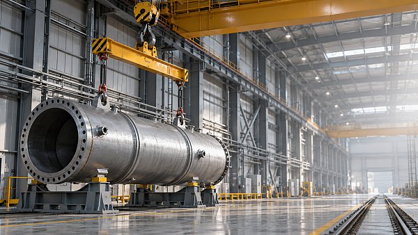
 Oct 23, 2026Selecting Lifting Equipment for Nuclear Component Transport: Key Safety CriteriaSelecting lifting machinery for nuclear component transport? Discover essential safety criteria, load control checks, and supplier requirements to guide confident procurement.
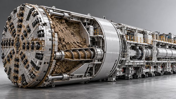
 Oct 22, 2026Tunnel Boring Machines in Southeast Asia: EPB vs. Slurry for Soft GroundCompare tunnel boring machines Southeast Asia projects rely on: EPB vs. slurry for soft ground. Discover how groundwater, settlement risks, and spoil handling shape the right choice.
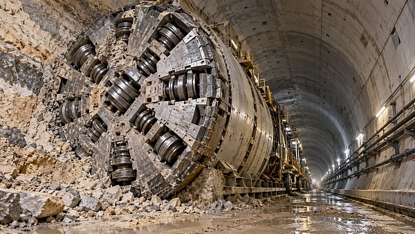
 Oct 21, 2026Choosing Tunneling Equipment for the Middle East: Rock, Soil, and GroundwaterCompare underground tunneling equipment Middle East projects need. Explore rock, soil, groundwater, and TBM options to reduce risk and make confident procurement decisions.
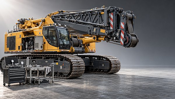
 Oct 20, 2026Which Heavy Machinery Maintenance Standards Apply to Your Construction Fleet?Discover which heavy machinery maintenance standards apply to your fleet. Clarify legal duties, OEM requirements, and inspection rules to reduce risk and keep equipment ready for work.
Related News

Ms. Elena Rodriguez
Weekly Insights
Stay ahead with our curated technology reports delivered every Monday.