
Selecting Nuclear Component Lifting Solutions for Safe Plant Maintenance Outages
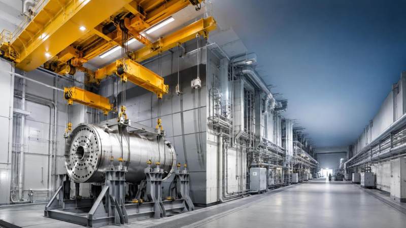
An outage lift can appear straightforward on the schedule: remove a heavy component, transfer it through a constrained route, complete inspection or replacement work, and reinstall it before the critical path closes. In practice, nuclear component lifting solutions plant maintenance teams select must perform under far tighter conditions than their rated capacity alone suggests. A crane or lifting device may be able to carry the load on paper yet still be unsuitable because of travel restrictions, hook height, building interfaces, load-path uncertainty, radiation controls, or insufficient recovery options.
The central decision is to select the lifting arrangement from the complete lift system, not from the component weight. That system includes the load, rigging, crane or gantry, support structure, travel path, control method, communications, inspection status, and outage sequencing. The preferred solution is usually the one that introduces the fewest unverified interfaces and gives the project team the most control over positioning, load transfer, and contingency response.
Start with the lift boundary, not the equipment catalogue
Before comparing mobile cranes, overhead cranes, gantries, strand jacks, or purpose-built lifting frames, define what the lift must actually accomplish. A request such as “lift and move a reactor-area component” is not yet a usable engineering basis. The project team needs to establish the physical and operational boundary of the work.
Begin with the component condition and configuration. Confirm the verified weight, expected center of gravity, approved lifting points, dimensions, transport restraints, and any temporary attachments that will be present during the lift. A component’s nominal drawing weight may not reflect retained fluids, shielding, tooling, packaging, accumulated deposits, or replacement parts installed before movement. Where center-of-gravity information is uncertain, the lifting plan should treat that uncertainty as a design issue rather than assuming equal sling loading.
Then map the route from initial support to final placement. Include every elevation change, door opening, hatch, turn, laydown position, transfer beam, and temporary support. The decisive constraint is often not at the pick point. It may be a low headroom transition, limited hook approach, floor loading restriction, overhead obstruction, or final alignment requirement inside a compartment where conventional crane movement becomes difficult.
Questions that should be answered before equipment selection
- What is the maximum credible lifted weight, including rigging, below-the-hook devices, temporary fixtures, and retained material?
- Where is the center of gravity in each handling orientation, and can it shift during the lift?
- Are the designated lifting lugs, trunnions, or attachment points suitable for the planned sling angles and load directions?
- Does the component require vertical lifting only, controlled rotation, horizontal translation, tilting, or precise final positioning?
- Which structures carry the equipment reactions, and have local floor, roof, beam, or foundation constraints been verified?
- What space is available for crane setup, rigging access, tag-line control, and operator visibility?
- What happens if the component cannot be set down at its intended location?
This definition stage prevents a common error: selecting the largest available crane and then trying to adapt the building, rigging, and work sequence around it. In outage work, a more compact arrangement with a shorter load path and fewer transfers may be safer and easier to manage than a higher-capacity unit operating near spatial limits.
Match the lifting method to the physical problem
Different lifting methods solve different constraints. The selection process should compare them against the actual movement required rather than treating them as interchangeable capacity sources.
An existing plant crane can reduce mobilization and simplify access, but it should not be assumed to be the best answer merely because it is already installed. Its rated capacity, operating envelope, current condition, inspection records, controls, hooks, hoist ropes, and supporting runway all need to fit the planned duty. The question is not whether the crane has lifted similar weight before; it is whether it can execute this lift at the required location, configuration, and control level.
Mobile and crawler cranes provide reach and capacity outside the building, but their site demands are substantial. Ground preparation, outrigger or track reactions, boom clearances, suspended-load control, and weather exposure may govern the plan. Their use becomes less attractive when the component must pass through a narrow building interface or when an external crane introduces an additional transfer that can be avoided with a temporary internal system.
Temporary gantries and hydraulic lifting arrangements are often selected because they create a controlled, repeatable path within limited headroom. Their value comes from controlled geometry, not simply lifting force. They require careful engineering of support conditions, alignment, connection points, synchronization, and temporary works installation. A gantry that is well suited for a vertical pick may be poorly suited for lateral movement unless a separate transfer method has been designed.
Capacity margins are only one part of the safety case
Rated capacity is an essential screening criterion, but it is not the final decision. The actual demand on a lifting system changes with radius, boom configuration, reeving, sling angle, side loading, dynamic effects, load sharing, and the weight of every item below the hook. A lifting plan should identify the governing configuration rather than rely on the maximum capacity listed for a different working condition.
Sling angle deserves particular attention. As sling legs move away from vertical, tension in each leg rises. A rigging arrangement that appears compact may impose larger forces on lifting lugs, shackles, spreader beams, and connection hardware than expected. Where geometry creates unfavorable angles, a spreader beam or strongback may be justified to control forces and maintain clearance from sensitive surfaces.
Load-path continuity matters just as much. Each point where the component is transferred—from a pedestal to a hook, from a hook to a transport frame, or from a crane to a temporary support—is a separate risk point. The team should know exactly when the load changes support, which device has control at each moment, and how the transition will be confirmed. Simultaneous load sharing between two hoists or two cranes requires a defined control philosophy; it should not be treated as an informal adjustment made during the lift.
Evaluate the work area as an operating environment
Nuclear maintenance spaces can make otherwise conventional lifting equipment difficult to use. Congested rooms, restricted access points, contamination boundaries, ventilation equipment, shielding, temporary services, and limited lines of sight all affect equipment choice. A lift that looks feasible in a two-dimensional layout can become impractical once hoist blocks, sling lengths, personnel access, and rigging installation clearances are included.
Headroom calculations should include the full vertical stack: crane hook or trolley geometry, hook block, shackles, slings or lifting links, beam depth where used, component lifting point elevation, and any clearance required over obstacles. Projects occasionally discover late in planning that the component can be raised but cannot clear the support, or that the hook cannot reach the required elevation without a different reeving arrangement.
Floor and structure checks must consider more than the component weight. Crane reactions, outrigger forces, gantry wheel loads, temporary support loads, and transport equipment can create concentrated demands that differ greatly from the load seen during normal operation. The supporting surface may also have embedded services, penetrations, coating limitations, or restricted zones that change where equipment can be placed.
Human factors are part of the equipment assessment. Can the operator see the load and destination? Are communication methods reliable through barriers or around corners? Is there room for riggers to connect and disconnect hardware without entering pinch points? Can the team maintain clear exclusion zones while retaining access for essential monitoring? Equipment with remote control or fine-positioning capability can help in some locations, but only when the control arrangement, feedback, and operating authority are planned in advance.
Build the outage sequence around lift readiness
A technically sound choice can still create schedule pressure if lifting readiness is treated as a late procurement or field activity. Long-lead rigging, custom frames, temporary steel, crane mobilization, access modifications, and required inspections should be identified early enough to avoid forcing a substitution during the outage.
Break the work into hold points that reflect real dependencies. Before the component is released, verify that the receiving location is ready, the route is clear, communications are tested, rigging identification is confirmed, and contingency supports are available. Before a critical lift begins, conduct a task-focused review that addresses the actual configuration of the day rather than repeating a generic lift briefing.
- Confirm the engineering basis. Reconcile current component information, approved lifting points, equipment configurations, support reactions, and route dimensions.
- Verify field conditions. Check that temporary structures, access openings, scaffolding changes, obstructions, and work boundaries match the plan.
- Stage tools in movement order. Place rigging, supports, guides, transport devices, and protective materials where they can be used without crossing the load path.
- Use a controlled initial take-up. Apply load gradually to confirm rigging seating, balance, clearance, and communication before committing to full travel.
- Define stop-work triggers. Unexpected movement, load tilt, communication loss, abnormal equipment response, route obstruction, or changed site conditions should have an agreed response before the lift starts.
The best schedule protection is not a faster lift. It is a lift method that has been rehearsed at the level appropriate to its complexity, supported by verified interfaces, and able to pause without leaving the component in an unstable or inaccessible position.
Do not overlook recovery and abnormal-condition planning
Every nuclear component lift should include a practical answer to a simple question: where can the load safely go if the planned movement must stop? The answer may be a rated temporary support, a designated laydown frame, a parked crane position, or a controlled hold point. “Keep it suspended until the issue is resolved” is rarely a robust recovery strategy.
Recovery planning should also address loss of primary equipment availability, misalignment at the receiving point, a rigging issue discovered after load transfer, restricted access caused by another outage activity, and an unexpected component balance condition. Not every scenario requires duplicate lifting equipment, but the team should distinguish between a manageable pause and a condition that requires engineered intervention.
Where the lift involves critical plant equipment, unusual geometry, multiple load paths, or temporary structural systems, independent review and site-specific authorization are appropriate parts of the selection process. The review should challenge assumptions about weight, center of gravity, structural capacity, equipment configuration, and operational sequence—not merely confirm that a capacity number exceeds the load.
A practical basis for the final selection
When competing nuclear component lifting solutions plant maintenance planners are evaluating appear technically feasible, choose the arrangement that best preserves control across the entire job: verified lifting interfaces, a clear and supported load path, manageable workspace demands, precise positioning capability, realistic outage integration, and a defined safe-state option. Higher nominal capacity does not compensate for poor access, unclear load transfer, or an unproven support condition.
A concise decision record should state why the selected method is preferable, what assumptions govern its use, which conditions would invalidate the plan, and what field verification is required before execution. That record gives engineering, operations, maintenance, and lifting personnel a common basis for recognizing when the lift remains within its intended boundary—and when it must be stopped and reassessed.
Related News
Related News

Structural Load Expert
Weekly Insights
Stay ahead with our curated technology reports delivered every Monday.