
Crane Performance Comparison: Load Capacity, Reach and Lifting Speed
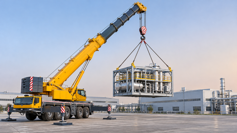
A useful crane performance comparison starts with a specific lift, not the largest capacity printed in a brochure. The right crane must lift the complete suspended load at the required operating radius and height, in a configuration that fits the site. Only after those conditions are met does lifting speed become a meaningful way to compare productivity.
These factors are linked. Moving a crane farther from the load can reduce its available capacity; adding a jib can provide clearance while changing the applicable load chart; and a faster hoist may offer little benefit if rigging, slewing or precise placement controls the cycle. A sound evaluation compares the entire lift path and working arrangement, not three headline figures in isolation.
Start with the load chart, not the maximum rating
A crane’s advertised maximum capacity describes a particular combination of radius, boom length, configuration and other chart conditions. It is not the weight the machine can lift at every point on a project. As operating radius increases, the load creates a larger overturning moment, and the permitted load generally decreases. Structural limits can also govern capacity, particularly with longer booms and jibs.
To compare candidates, identify the most demanding combination of load, radius and height along the planned path. That may occur when the load is picked, when it is set down, or during a swing between the two. A component that starts close to the crane can become critical if it must be slewed over a larger radius before placement.
The load used for the comparison must include more than the component’s shipping weight. Hook blocks, slings, shackles, spreader beams and other suspended lifting equipment all contribute to the load handled by the crane. The applicable chart and its notes establish how to account for each item. On some lifts, the rigging needed to control a long or flexible component also consumes valuable hook height.
Compare the resulting load with the rating for the actual configuration: boom or jib arrangement, counterweight, support condition, operating area and any other conditions identified in the manufacturer’s documentation. A crane with a higher maximum rating can have a lower allowable load at the project’s critical radius than a machine with a smaller headline rating.
Reach is a combination of radius, height and clearance
“Reach” can refer to horizontal working radius, hook height or the ability to place a load past an obstruction. These are related, but they are not interchangeable. A long boom does not automatically provide the capacity needed at a long radius, and the highest attainable hook position may not leave enough room for the rigging or the component itself.
Build the geometry from the load’s path. Establish the crane’s possible positions, the pickup and landing points, the required hook height and the clearances around existing structures. Then consider how boom angle, jib offset and load orientation affect the movement. For a tall vessel placed inside a plant, clearance over the surrounding structure may govern crane selection even when the component is relatively light. For a dense module placed at ground level beyond an obstruction, radius and chart capacity may govern instead.
Adding a jib can solve a clearance problem, but it changes the crane configuration and the relevant capacity chart. It can also affect assembly time, transport requirements and sensitivity to wind. The correct comparison is therefore between complete, feasible configurations, rather than between bare boom lengths.
Allow for the space required by the hook block and rigging when checking clearance. A drawing that shows the hook reaching a landing point does not, by itself, establish that the load can be held in the required orientation or lowered into place without interference.
Read lifting speed in the context of the whole cycle
Published hoist speeds are useful for screening, but they need careful interpretation. Speed can vary with load, drum layer, reeving and the operating mode described in the equipment specifications. A value associated with light or no-load operation should not be treated as the speed available while lifting a heavy component. More parts of line can support a heavier load within the hoist and rigging limits, but can also reduce hook travel speed for a given rope speed.
For repetitive work, compare cycle time rather than maximum line speed alone. A cycle can include attaching the load, taking up slack, hoisting, slewing, travelling or luffing where permitted, positioning, releasing the load and returning the hook. Some movements may overlap when the crane and lift plan allow it; others require deliberate sequencing.
For example, a crane with a faster hoist may offer little practical advantage on a congested industrial site if precise positioning and rigging dominate each cycle. Conversely, on repetitive lifts with uncomplicated rigging and a clear path, loaded hoist speed and the ability to coordinate movements can make a meaningful difference. Control at low speed matters as well: placing a component accurately can be more valuable than reaching the landing area a few seconds sooner.
When comparing specifications, use the same load, hook arrangement and travel distance for each candidate. Include expected setup and rigging time in the operational comparison, particularly if the project has only a small number of heavy lifts.
Compare crane types against the work sequence
Crane categories provide a useful starting point, but individual configurations and load charts determine whether a particular machine can perform the lift.
For wind power or large industrial components, a crawler crane may provide a suitable combination of height and capacity, but the project must also accommodate its assembly and ground-bearing requirements. For lifts spread across multiple locations, a mobile crane’s shorter relocation sequence may outweigh the benefit of a larger machine that takes longer to configure. Neither conclusion holds without checking the actual loads and site layout.
Site conditions can determine which crane is feasible
Ground support: A crane that meets the load chart still needs adequate support. Outrigger reactions or crawler track pressures depend on the lift and configuration; soil condition, underground services, excavations and nearby slopes affect the support arrangement. Use crane-specific reaction information to develop the ground-bearing assessment and any required mats or engineered support.
Space and access: Check the route for the crane and its supporting loads, then assess assembly areas, outrigger or track footprint, tail swing and clearance from structures. A larger crane may reduce the working radius from one position but require more room for setup. The comparison should also include where components, counterweights and rigging will be staged.
Wind and load shape: A large, light component can be difficult to control even when its weight is well below chart capacity. Wind limits depend on the crane, configuration, load characteristics and lift procedure. The exposed area and shape of the load matter alongside wind speed; the limiting condition may come from load control as well as the crane’s operating limits.
Configuration changes: A project may need several boom lengths, radii or crane positions. Reconfiguring between lifts can add transport, labour and downtime. A crane that handles every lift in one arrangement may be the more productive choice, provided it still meets each lift’s capacity and clearance requirements.
A practical comparison for a critical lift
Consider a project placing a large module behind an existing structure. One candidate can be positioned close to the module’s pickup point but must work at a longer radius to reach the landing point. Another requires a more involved setup, yet can be placed where its radius remains shorter throughout the lift.
The first comparison is not their maximum rated capacity. It is the allowable load at each significant point in the movement, using the proposed boom, counterweight and support configuration. The landing point may control the first crane’s capacity, while clearance over the structure may control the second crane’s boom or jib selection. Both must have sufficient hook height after the rigging and module dimensions are included.
Once both arrangements have passed those checks, compare their operational costs and schedule effects: access, ground preparation, assembly, support equipment, lift duration and removal. A faster hoist matters if it changes the project sequence; for a single critical placement, setup and controlled positioning may have a larger effect on the schedule.
What to request before making the selection
Give each prospective supplier the same lift information: component weights and dimensions, lifting points, rigging assumptions, pickup and landing coordinates, required clearances, site access and ground constraints. Ask for the proposed crane configuration and the applicable load chart entries for the critical positions, together with assembly needs and support reactions.
Review the whole operating range rather than accepting a single capacity figure. Confirm that the proposed arrangement accounts for the suspended rigging, maintains clearance throughout the lift and leaves an appropriate margin under the lift plan. Where conditions or the load path change, the comparison must be revisited for the new configuration.
The final choice is the crane that can perform the planned work within its documented limits and site constraints, with a work sequence that makes sense for the project. Capacity establishes feasibility; reach establishes access; lifting speed helps distinguish productive options once both are satisfied.
Have questions about this sector analysis, or seeking best practices specific to your niche? Drop us a line below and let the senior consultants at TF-Strategy assist you.
Related News
 Nov 11, 2026Choosing Equipment Capacity for Different Workloads and ApplicationsExplore equipment application by capacity to match machines to real workloads, reduce bottlenecks and choose cost-effective solutions with confidence.
 Nov 10, 2026Crane Performance Comparison: Load Capacity, Reach and Lifting SpeedCrane performance comparison made practical: evaluate load capacity, reach and lifting speed to choose the right crane for your site and work sequence.
 Nov 09, 2026Heavy Equipment Technology Systems: Telematics, GPS and Machine ControlExplore heavy equipment technology systems, from telematics and GPS to machine control, and learn how to choose the right tools for your fleet and site.
 Nov 10, 2026Selecting a Four-Axle Rear Dump Semi-Trailer for Aggregate HaulingExplore dump special trailers for aggregate hauling. Learn how to compare legal payload, body durability and tipping safety before choosing a four-axle rear dump semi-trailer.


Ms. Elena Rodriguez
Weekly Insights
Stay ahead with our curated technology reports delivered every Monday.