
Heavy Equipment Technology Systems: Telematics, GPS and Machine Control
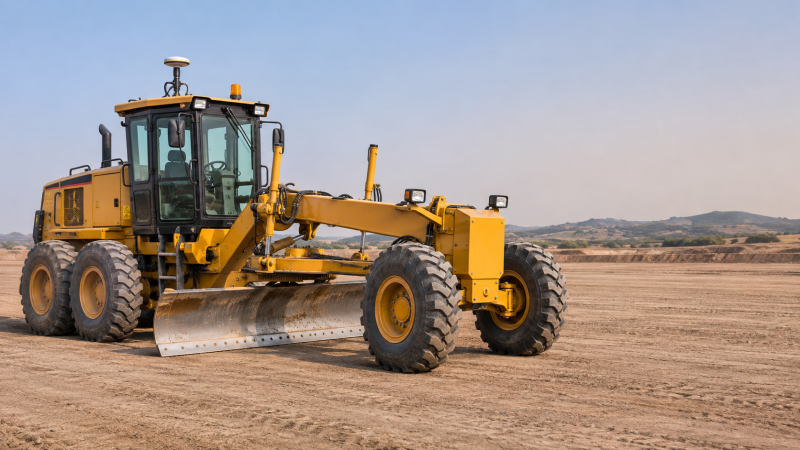
A fleet manager may know that an excavator is on site but not whether it is working, idling, or due for maintenance. On the same project, a grader operator may need to meet a design elevation without relying on repeated manual checks. These are different problems, and they call for different heavy equipment technology systems: telematics reports machine and operational data, GPS-based positioning establishes location, and machine control uses positioning and machine geometry to guide or automate selected movements.
The systems can share data, but they are not interchangeable. A machine location on a fleet dashboard is not necessarily accurate enough for grading, and an automated blade does not by itself explain fuel consumption or maintenance history. Understanding that distinction helps researchers assess where each technology contributes and what conditions limit its usefulness.
Three systems, three operational questions
GPS is one satellite navigation system; GNSS is the broader term for satellite constellations used for positioning. Equipment discussions often use “GPS” as shorthand, although a receiver may use signals from more than one constellation. The name alone does not indicate the accuracy available at the machine.
Telematics turns machine signals into fleet information
A telematics system collects data from a machine through an onboard device, often drawing on the equipment’s electronic control systems and additional sensors. It transmits available information to software where users can review individual machines or a fleet. Depending on the equipment and configuration, that information may include engine hours, location, fuel-related readings, fault codes, operating states and service reminders.
Consider a machine that appears to have high engine hours but limited production. Telematics may show extended idle time, helping a manager investigate whether the cause is queuing, warm-up requirements, scheduling or another operating constraint. The data identifies a pattern; it does not explain the cause without context. An idle classification can also depend on how a particular machine or software platform defines that state.
Maintenance alerts are signals, not diagnoses
Fault codes and threshold alerts can help teams prioritize inspections, but an alert does not always identify the failed component or establish how urgently a repair is needed. A technician may need to consider the machine’s symptoms, fault history and manufacturer guidance before acting. Likewise, a missing alert is not proof that the equipment is healthy: a sensor may be absent, a message may not have been transmitted, or the relevant condition may not be monitored.
Service planning also depends on the meaning of the underlying meter. Engine hours, machine-on hours and actual working hours are not necessarily the same. Before comparing utilization or scheduling maintenance across mixed fleets, check which meter each machine supplies and how the software calculates its reports.
Connectivity changes what a dashboard can show
Remote mines, tunnels and deep excavations can have limited cellular coverage or obstructed satellite signals. Some onboard devices store data and send it later when a connection returns; others have different capabilities. A stale location or old fault timestamp may therefore reflect a transmission gap rather than the machine’s present condition.
When evaluating a system, distinguish the time an event occurred from the time it reached the platform. Ask what data is retained during an outage, how long it can be stored, and whether alerts still reach the people responsible for responding.
Positioning: a location is not automatically a grade reference
A basic satellite-derived position can be useful for locating assets, reviewing movement or creating a geofence around a work area. Those tasks generally have different accuracy requirements from placing a cutting edge against an engineered surface. For precision work, GNSS receivers may use correction data from a local base station or a correction service. The correction method, receiver, site geometry and signal quality all influence the resulting position.
A position also needs a meaningful reference. Construction designs use coordinate systems, elevations and site-specific transformations. If a machine receives a valid position but uses the wrong coordinate system or vertical reference, the displayed relationship to the design can be wrong. Site setup should therefore be checked against known control points using the project’s established survey procedures.
Satellite positioning has physical limits. High walls, trees, structures and the machine itself can obstruct or reflect signals. Underground, satellite signals are generally unavailable, so a TBM cannot rely on ordinary GNSS reception at the cutterhead. Tunnel guidance instead uses other surveying and guidance methods suited to the alignment and working environment. Surface GNSS may still support related survey activities where reception is available.
Machine control connects the design to the working tool
Machine control compares the position and orientation of a machine’s working tool with a target surface or alignment. On a dozer or grader, that tool is typically the blade; on an excavator, it is the bucket or another attachment. The system combines a design or target reference with measurements from positioning equipment and machine-mounted sensors.
The operator may see a display showing whether the tool is above, below or on the target. In some configurations, the system can automatically adjust supported hydraulic functions while the operator remains responsible for operating the machine. The extent of automation varies by machine and system; “machine control” should not be assumed to mean an autonomous vehicle.
Two-dimensional and three-dimensional control
2D systems generally work from a local reference, such as a set slope, elevation reference or laser plane. They can suit tasks where that reference adequately describes the work, but they do not necessarily know the tool’s full position against a complex digital terrain model.
3D systems use a position and a digital design or surface model to guide the tool across a site. Depending on the application, positioning may come from GNSS, a robotic total station or another compatible method. A total station can be useful where satellite reception is obstructed or where the job requires a different positioning approach, although it introduces its own setup and line-of-sight requirements.
The choice is not simply between “basic” and “advanced.” A long, uniform slope may need a different reference arrangement from a road formation with changing elevations and crossfalls. The design deliverable, required tolerance, visibility and survey control determine which arrangement can be used reliably.
Why a correct design can still produce an incorrect cut
Machine control calculates the working edge from measured positions, angles and configured dimensions. Wear, a changed bucket, an incorrectly entered attachment dimension or an out-of-date calibration can affect that calculation. A model can also be correct in isolation but unsuitable for the current task if the wrong revision, layer or coordinate transformation is loaded.
Before relying on guidance, teams normally verify the setup against independent site checks. A practical sequence is to confirm the approved design and coordinate reference, check the machine and attachment configuration, then compare the indicated tool position or finished surface with a known reference. A discrepancy should be investigated before continuing work to a demanding tolerance; it should not be corrected by guessing an offset.
Where the systems meet on a worksite
On an earthmoving operation, a digital design can guide an excavator or dozer while telematics reports machine hours and operating states. Position data may serve both functions, but the position shown on a fleet map may come from a different receiver or processing path than the one used for machine control. Two screens showing the same machine do not establish that they use the same accuracy, update rate or coordinate reference.
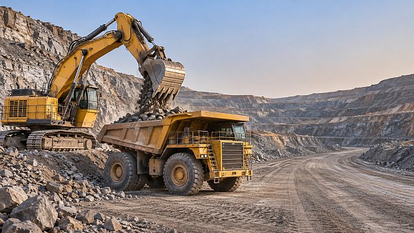
Mining equipment illustrates another distinction. A haul truck’s location and machine data can support dispatching, utilization analysis and maintenance planning. Those functions may exchange information with production systems, but payload, travel time and loading status depend on the sensors and integrations in place. Location alone cannot establish how much material was moved.
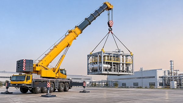
For a crawler crane, positioning may assist with site awareness or records, while the crane’s rated capacity and operating configuration remain central to lift planning. A location feed or remote dashboard is not a substitute for the crane’s load information, approved lift plan, ground assessment or the operator’s safety responsibilities.
Assessing a system without confusing features with outcomes
Start with a specific operational question. “Which machines exceeded a service interval?” requires dependable meter readings and maintenance records. “Is the blade at the planned elevation?” requires a suitable reference, calibrated machine geometry and a verified design. “Why was output low?” may require production, cycle and scheduling information that neither a location feed nor engine hours can supply alone.
Then examine the data path from the machine to the person using it:
- Source: Identify the sensor or machine signal behind each field. Confirm whether the value is measured, calculated, entered manually or inferred from an operating state.
- Timing: Check update frequency, event timestamps and expected behavior during communication outages. A delayed report may be adequate for maintenance history but unsuitable for an immediate response.
- Reference and accuracy: For positioning or grade work, establish the required tolerance, coordinate system, correction source and independent verification method.
- Compatibility: Confirm which machines, attachments, software formats and functions are actually supported. A connection that supplies hours may not expose payload or detailed fault information.
- Action: Decide who reviews the output and what they can do with it. An alert has limited operational value if no one owns the response or can verify its cause.
Ownership and access to information deserve the same scrutiny as technical compatibility. Establish who can view and export machine data, how records are retained, and what happens when equipment changes hands or a subscription ends. For mixed fleets, consistent definitions and export formats matter when comparing utilization across machines from different manufacturers.
Costs also extend beyond onboard hardware. Installation, correction services, connectivity, software access, calibration, operator training and maintenance of digital models can all affect total cost of ownership. A meaningful assessment compares those requirements with the particular measurement or control task—not with an assumption that adding more data will automatically improve performance.
Have questions about this sector analysis, or seeking best practices specific to your niche? Drop us a line below and let the senior consultants at TF-Strategy assist you.
Related News
 Nov 11, 2026Choosing Equipment Capacity for Different Workloads and ApplicationsExplore equipment application by capacity to match machines to real workloads, reduce bottlenecks and choose cost-effective solutions with confidence.
 Nov 10, 2026Crane Performance Comparison: Load Capacity, Reach and Lifting SpeedCrane performance comparison made practical: evaluate load capacity, reach and lifting speed to choose the right crane for your site and work sequence.
 Nov 09, 2026Heavy Equipment Technology Systems: Telematics, GPS and Machine ControlExplore heavy equipment technology systems, from telematics and GPS to machine control, and learn how to choose the right tools for your fleet and site.
 Nov 10, 2026Selecting a Four-Axle Rear Dump Semi-Trailer for Aggregate HaulingExplore dump special trailers for aggregate hauling. Learn how to compare legal payload, body durability and tipping safety before choosing a four-axle rear dump semi-trailer.
Ms. Elena Rodriguez
Weekly Insights
Stay ahead with our curated technology reports delivered every Monday.