
Crane Selection for Petrochemical Turnarounds: Capacity, Radius, and Site Access

Select a crane for a petrochemical turnaround by matching its rated capacity to the complete suspended load at every planned working radius, then confirming that the required configuration can enter, assemble, and operate within the site. Nameplate capacity alone cannot establish suitability. A crane with a higher maximum rating can still be unsuitable because its boom geometry, counterweight envelope, support reactions, or access requirements conflict with the lift location.
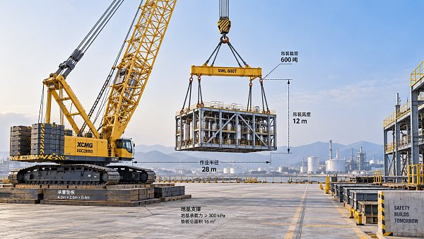
The selection should resolve three connected questions: whether the crane can carry the load through the full lift path, whether that configuration physically fits, and whether the supporting ground and access route can accommodate it. For petrochemical lifting solutions, these questions often determine whether an exchanger bundle, vessel section, or maintenance component can be removed within the shutdown sequence.
Define the suspended load before comparing cranes
The starting weight must represent the component in its actual lifting condition. Equipment drawings can describe an empty assembly while the removal load includes retained liquid, deposits, insulation, attached platforms, or temporary steelwork. An exchanger bundle also presents a different lifting condition from the complete exchanger. Establish which parts remain attached and what draining, cleaning, or dismantling will occur before lifting.
Weight uncertainty needs an engineering basis. An arbitrary allowance does not resolve an unidentified internal inventory or an undocumented modification. Where records disagree, reconcile drawings, maintenance history, and available measurements before treating the load as confirmed. A bounded weight estimate should retain its uncertainty in the capacity assessment.
The capacity calculation must also account for slings, shackles, spreader beams, lifting frames, and the hook block according to the manufacturer's load-chart conventions. Some charts express gross rated capacity and require specified deductions to determine the allowable payload. Follow those conventions consistently so that accessories are neither omitted nor counted twice.
Center of gravity affects the rigging arrangement and load orientation. An offset center of gravity creates unequal sling loads and can tilt the component as it clears its supports. That tilt changes the clearance envelope and potentially the required hook position. Sling angles, lifting-point capacity, and spreader geometry therefore belong in the initial crane selection, rather than being left until the crane arrives.
Working radius follows the entire lift path
Working radius is the horizontal distance from the crane's axis of rotation to the vertical load line, interpreted using the manufacturer's chart instructions. Measuring from an outrigger, track edge, or boom foot produces the wrong basis for capacity selection. Site surveys should locate the crane's rotation center relative to the actual lifting points and destination.
The pickup radius is only one position. A component might need to move outward to clear a pipe rack before it can slew toward the laydown area. The placement point might sit farther from the crane than the original equipment foundation. Evaluate the intermediate positions as well as the endpoints, including any movement needed to control orientation or avoid adjacent equipment.
The controlling position is the one with the least acceptable capacity margin for its actual configuration. It is often the largest radius, but changes in operating sector, boom arrangement, or permitted movement can make another position more restrictive. A lift-path drawing should connect each significant position to the applicable chart rating.
Use loaded geometry when assessing clearance. Boom deflection and rigging stretch affect the relationship between the hook, load, and nearby structures. Include positioning tolerances rather than assuming the crane will stand exactly on a nominal survey point. A small outward displacement can consume the available margin on a steeply declining section of the capacity chart.
Read the chart as a configuration-specific limit
A capacity value is valid only for the configuration identified by the chart. Relevant variables include boom length, jib arrangement, counterweight, outrigger extension or track configuration, operating sector, and any required auxiliary equipment. Similar-looking crane models or different counterweight packages are not interchangeable.
For a telescopic crane, the chart can distinguish between boom extension arrangements as well as overall boom length. For a lattice-boom crane, main boom, fixed jib, and luffing jib configurations have separate geometry and capacity constraints. A quoted rating without its configuration details is insufficient for comparison.
Capacity is also subject to hoisting-system limits. The selected hook block, number of rope parts, permissible line pull, and available rope length must support the load and required hook travel. Adequate chart capacity does not compensate for an unsuitable reeving arrangement. More rope parts also affect hoisting speed and block geometry, which can matter during a tightly sequenced removal.
Read the chart notes alongside the tabulated values. They establish the applicable conditions, deductions, and restrictions. Apply the project's lift-classification and utilization requirements where specified; there is no universal utilization percentage that makes every petrochemical lift acceptable. A documented margin should address the actual uncertainties in weight, radius, and execution.
Boom clearance can eliminate an otherwise adequate crane
Hook height must accommodate the load, rigging height, hook block, and the clearance needed to lift free of supports. A spreader arrangement that protects a fragile component can increase the required height substantially. This can force a longer boom or a different jib configuration, changing the available capacity at the same radius.
Plot the boom and load envelopes against pipe racks, columns, cable trays, platforms, and overhead services. Sufficient hook height does not establish sufficient boom clearance. The boom can intersect an obstruction while the hook remains above the lifting point, especially when reaching over a rack to equipment positioned close behind it.
A luffing jib can provide useful reach and geometry around obstructions, but its benefit must be tested against its chart, assembly requirements, and rear working envelope. A longer main boom is likewise not an automatic improvement: it changes capacity, deflection, and wind exposure. Choose the configuration that satisfies the full geometry rather than adding reach without evaluating its consequences.
Removal clearance deserves particular attention. Equipment that fitted during original construction might now be surrounded by operating pipework or later additions. Confirm the release path after bolts, connections, and temporary supports are removed. The crane should lift a freely released component; it should not be selected on the assumption that its hoist will overcome an unquantified extraction or snagging force.
Crawler and mobile cranes solve different site constraints
The comparison becomes useful once load, radius, and clearance are defined. Broad labels such as “heavy lift” or “restricted site” do not establish which crane type fits. The decisive differences are the space required to establish the working configuration and the movements permitted during the turnaround.
A crawler becomes attractive when several demanding lifts can share an established working area and its assembly footprint is available. An all-terrain crane is often practical where road access is usable and individual lift positions can accommodate the required outriggers. Partial outrigger extension is acceptable only where an applicable manufacturer rating covers the exact setup.
Do not assume a crawler can travel with the suspended load merely because it runs on tracks. Loaded travel requires an approved configuration and assessment of route geometry, bearing conditions, slope, and movement limits. Likewise, mobility between locations does not imply that a road-going crane can perform the same loaded movement.
Ground support must follow the reactions
Average machine weight divided by total contact area is an inadequate basis for support design. Outrigger loads change as the crane slews, and crawler track pressure is not uniformly distributed. Obtain reactions for the proposed configuration and relevant load positions, including unloaded or assembly conditions where they govern.
The ground assessment must connect those reactions to a credible load-bearing model. Pavement thickness alone says little about buried trenches, culverts, drains, cable ducts, or backfilled excavations. Petrochemical sites frequently combine hard surfacing with underground infrastructure, so an apparently sound setup area can contain a localized weakness.
Mats spread load only when their stiffness, dimensions, and support conditions allow them to do so. Treating the entire mat footprint as effective bearing area without evaluating load distribution can overstate its benefit. The assessment also needs to address settlement and differential movement, since crane level affects the validity of the operating conditions.
Ground preparation can change the crane choice. Moving the setup onto suitable support might increase radius enough to require a larger configuration. Conversely, a verified support arrangement closer to the load can make a smaller crane feasible. Resolve location and ground engineering together rather than freezing the crane size first.
Access includes delivery, assembly, and departure
Survey the route using the dimensions and axle loads of the actual transport arrangement. Gate width is only one constraint. Turning geometry, overhead pipe bridges, grades, road edges, and pavement capacity can prevent a crane or its support vehicles from reaching the intended position.
The crane's arrival configuration can differ substantially from its operating configuration. Counterweight trucks, boom trailers, an assist crane, and rigging deliveries need unloading positions and a workable sequence. A setup area that fits the assembled crane may still be too small to build it.
Draw the occupied area across time, including boom assembly or lowering, counterweight handling, tail swing, and component laydown. Superlift arrangements need explicit assessment of their additional equipment and movement envelope. Space shared with scaffolding, maintenance access, or an emergency route cannot be assumed continuously available.
The removed component also needs a destination. If its laydown location blocks crane dismantling or the transport route, the planned lift creates a later obstruction. Include the departure sequence while choosing the initial setup.
Resolve the controlling uncertainties before commitment
A useful technical comparison records each candidate's exact configuration, chart capacity at controlling positions, suspended-load basis, clearance envelope, support reactions, and assembly requirements. Separate confirmed dimensions from unresolved assumptions. This exposes whether apparent capacity margin relies on an unverified weight, unavailable counterweight, or setup position that cannot be occupied.
Wind assessment should account for load shape and projected area alongside the manufacturer's limits. A broad vessel section or lifting frame can impose a different constraint from a compact load of the same mass. Nearby live equipment, exclusion boundaries, and visibility also shape the permitted lift path and positioning method.
For tandem or tailing operations, assess load sharing throughout the rotation or transfer. The load on each crane changes with geometry, and small coordination errors can redistribute it. A fixed split of the total weight is insufficient unless the engineered arrangement supports that assumption.
The selected configuration should remain traceable to the verified site layout and lift sequence. If the crane position, component condition, rigging, or laydown destination changes during the shutdown, reassess the affected chart positions and clearances before execution. Those changes can alter the selection even when the component's nominal weight remains unchanged.
Related News
 Oct 15, 2026Crane Selection for Petrochemical Turnarounds: Capacity, Radius, and Site AccessExplore petrochemical lifting solutions cranes can deliver, with expert guidance on capacity, working radius, and site access to help you plan a safer, more efficient turnaround.
 Oct 14, 2026High-Capacity Heavy Lifting Solutions: Matching Load, Radius, and Ground ConditionsDiscover heavy lifting solutions high capacity projects demand—compare load charts, working radius, and ground conditions to select a feasible, cost-effective system.
 Oct 13, 2026OEM Equipment Suppliers in Europe: Vetting Quality, Lead Times, and SupportCompare OEM equipment Europe suppliers on quality, lead times, and after-sales support. Discover practical vetting steps to reduce downtime and buy heavy equipment with confidence.
 Oct 12, 2026How to Assess a High-Altitude Mining Equipment Manufacturer for Remote ProjectsHigh altitude mining manufacturer assessment guide: compare derating, cold-climate reliability, remote service, parts resilience, and lifecycle risk for smarter project decisions.


Ms. Elena Rodriguez
Weekly Insights
Stay ahead with our curated technology reports delivered every Monday.