
High-Capacity Heavy Lifting Solutions: Matching Load, Radius, and Ground Conditions
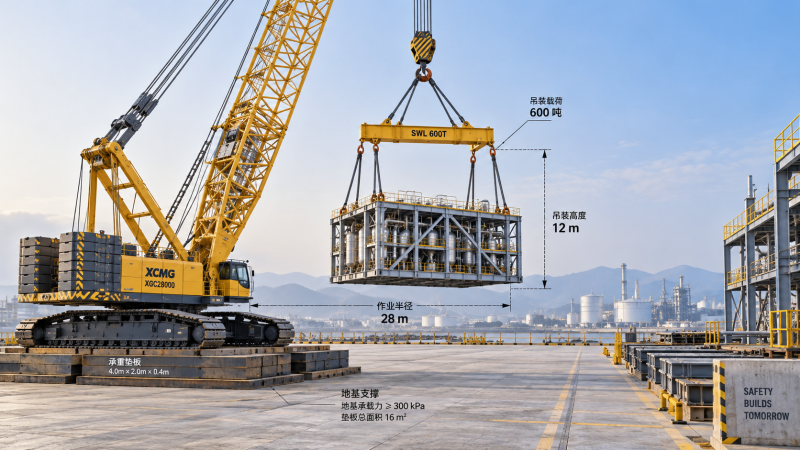
A high-capacity lifting system is suitable only when its approved configuration can handle the complete suspended load throughout the lift path, within the required working radius, and on ground capable of supporting the resulting reactions. A crane’s advertised maximum capacity provides little basis for selection until those conditions are defined. A smaller machine positioned closer to the load may offer a more workable solution than a larger crane operating at an extended radius.
For technical evaluators, the first decision is whether the proposed equipment and site arrangement form a feasible lifting method. That requires three connected checks: establish the load and geometry, verify the relevant manufacturer capacities, and demonstrate that the support conditions remain acceptable during every planned movement. Only then does a comparison of mobilization cost, schedule, and equipment availability become meaningful.
Define the load and the full lift path before choosing capacity
The component’s stated weight is only the starting point. Slings, shackles, lifting beams, spreaders, temporary attachments, and other suspended equipment can materially affect the capacity available for the payload. Hook blocks and certain accessories may also require deductions, depending on how the manufacturer defines the load chart. The calculation must follow that chart’s conventions so each item is accounted for once.
Weight confidence matters as much as weight magnitude. A documented fabricated weight, an early design estimate, and a shipping weight that includes packaging are different inputs. Equipment containing liquids, residual material, internal assemblies, or temporary steelwork needs a clearly defined lifting condition. Where uncertainty remains, the engineering assessment should address it explicitly rather than conceal it within an arbitrary allowance.
The center of gravity determines how the load hangs and how forces distribute through the rigging. An offset center of gravity can place unequal loads on sling legs and lifting points, even when the overall suspended weight appears comfortably within crane capacity. Sling angles also affect leg tension. A crane capacity check therefore needs a compatible rigging design, verified lifting points, and confirmation that the component can withstand the intended handling loads.
Working radius is the horizontal distance from the crane’s axis of rotation to the vertical load line. It is not simply the clearance between the crane and the edge of the component. Evaluate the radius at pickup, through slewing or other permitted movements, and at final placement. Account for loaded boom deflection using the manufacturer’s planning method; a layout based only on unloaded geometry can understate the operating radius.
The farthest point is not automatically the only governing condition. A lift can encounter different capacity limits as boom angle, configuration, operating sector, or support conditions change. Clearance above structures may demand a longer boom or a luffing jib, while a restricted landing position may force the crane farther away. These requirements can alter the equipment choice before payload weight changes at all.
A useful initial lift definition includes:
- The component weight, its source, center of gravity, and any unresolved weight uncertainty.
- The rigging arrangement and all chart deductions applicable to the proposed configuration.
- Pickup and placement coordinates, elevations, and the planned load path.
- Required boom clearance, load orientation, and potential obstructions.
- Whether the operation includes tailing, load transfer, or travel with a suspended load.
This information allows suppliers to propose configurations against a shared task. Without it, quotations for nominal crane tonnage may represent substantially different capabilities.
Read the load chart as a configuration-specific operating limit
A load chart applies to a defined machine arrangement. Boom length, jib configuration, counterweight, crawler stance or outrigger extension, operating sector, and auxiliary equipment can all affect the permitted load. For a crane using a suspended ballast system, the ballast arrangement and required operating space become part of the assessment. Capacity taken from a different arrangement cannot establish suitability.
Request the chart and configuration details for the actual proposed machine. Check that the chart covers the required radius and geometry, and follow its instructions for values between listed points. Do not assume that capacity can be interpolated or that a chart for stationary lifting permits travel. Manufacturer notes and restrictions carry the same decision weight as the capacity figures.
The comparison should put the chart capacity and calculated load on the same basis. If the chart expresses gross capacity, the relevant suspended equipment and required deductions must be included. Where a supplier presents a net payload capacity, ask for the underlying deduction schedule. This prevents a seemingly adequate proposal from relying on omitted rigging weight or inconsistent treatment of the hook block.
Consider an illustrative lift in which the component, rigging, and applicable chart deductions total 220 tonnes. If the verified capacity at the governing radius is 250 tonnes, the arithmetic utilization is 88 percent. That calculation describes the relationship between those two figures; it does not establish that the lift is acceptable. Weight uncertainty, configuration accuracy, wind restrictions, ground behavior, and project-specific lifting requirements still need assessment. No single utilization percentage supplies a universal approval threshold.
Available margin is most useful when evaluated against identifiable sources of change. How much additional radius would result from moving the crane outside an excavation exclusion zone? Could the final rigging design require a heavier spreader? Does the proposed boom arrangement preserve enough clearance under load? A solution with limited tolerance for these changes may create expensive redesign even though the first calculation passes.
Wind deserves particular attention when lifting large components. Vessels, turbine components, modules, and other loads with substantial exposed area can develop forces that affect control and crane loading. A general site wind limit may not satisfy the manufacturer’s requirements for that load shape and boom arrangement. The lift plan should apply the relevant wind criteria and define how conditions will be monitored and when the operation must stop.
Dynamic effects also belong within the approved method. Acceleration, braking, sudden release of a snagged load, and uncontrolled load movement cannot be covered by casually subtracting an extra percentage from chart capacity. Follow the equipment instructions and the engineered operating procedure. For multi-crane lifts, each crane’s share must be assessed through the planned sequence, including changes in geometry and load distribution during transfer.
Ground conditions can determine the lifting solution
The ground assessment should begin while crane positions are still being developed. A technically capable crane can become impractical if its reactions exceed what the site can support or if ground improvement consumes the available schedule. Moving to a larger machine may increase support demands, transport requirements, and assembly space without resolving the underlying constraint.
For crawler cranes, dividing total machine weight by track area provides only a preliminary average pressure. Actual track reactions and pressure distributions vary with the suspended load, boom direction, counterweight arrangement, and operating condition. One track or part of a track can experience substantially greater loading than the average suggests. Obtain reaction information for the relevant lift cases and use it in the platform design.
For cranes supported on outriggers, assess the governing individual outrigger reactions. Equal division of total weight among the supports is an inadequate design basis. The reaction pattern changes as the crane slews and lifts, and the highest support force may arise at a specific stage of the operation. Mat or foundation design must reflect these cases.
The geotechnical input must describe the proposed support locations. Nearby investigation results may miss local fill, buried trenches, drainage lines, voids, or weak layers. Groundwater, recent excavation, rainfall, and adjacent slopes can also change the suitability of a platform. An allowable bearing value needs a clear relationship to the ground profile, loading footprint, and settlement criteria used in the assessment.
Bearing resistance alone does not answer the whole question. Excessive or uneven settlement can move the crane outside its permitted level condition. Ground close to an excavation or retaining structure may require assessment of wider stability and structural effects. Underground services and culverts need their own protection checks rather than being treated as ordinary soil.
Mats spread load only as effectively as their stiffness, arrangement, contact conditions, and supporting ground allow. Increasing mat area does not guarantee that the full area carries load uniformly. The support design should check the mats themselves, local contact pressures, underlying ground behavior, and any bridging over weaker areas. A quoted mat package without these checks leaves a major part of the lifting system unresolved.
Where travel with a load is proposed, the assessment extends along the route. Surface transitions, slopes, turning movements, underground structures, and changing ground conditions must be compatible with the manufacturer’s permitted travel configuration. For cranes that require large counterweight or ballast arrangements, verify the space and support conditions those systems need throughout the planned operation.
Choose the system around site geometry and execution constraints
Crawler cranes can be strong candidates where substantial capacity, long reach, repeated lifts, or approved travel with load are required. Their suitability depends on having enough space for assembly, boom laydown, counterweight handling, and an engineered working platform. The footprint of the lifting operation extends well beyond the tracks.
Large mobile cranes deserve consideration where access and support locations suit the machine and the lifting sequence benefits from their setup arrangement. Check the exact outrigger configuration, operating sector, boom or jib arrangement, and access route. A shorter mobilization plan has little value if the required support positions conflict with buried infrastructure or site traffic.
Engineered gantries, strand-jack systems, and skidding arrangements may be viable when the movement follows a constrained path or conventional crane access is difficult. Their selection shifts attention toward lifting points, temporary support structures, load transfer, synchronization, and structural reactions. They can solve certain geometry problems, but they require a complete installation and movement design.
Before escalating equipment size, examine whether the lift arrangement can be improved. Relocating a laydown area, opening a closer crane position, changing the installation sequence, or reducing an avoidable clearance requirement may reduce the governing radius. Any proposed change to component assembly or lifting orientation must remain compatible with structural integrity and construction requirements.
Compare total execution cost once feasible options have been established. Include transport, assembly and dismantling, ground preparation, temporary works, assist cranes, ballast handling, and any restrictions imposed on surrounding work. Weather exposure and the time needed to complete each lifting stage also influence schedule reliability. A lower equipment rate can be outweighed by a more demanding site arrangement.
The most useful supplier submission is an auditable lift proposal: the exact machine configuration, applicable load charts, load and deduction schedule, lift geometry, support reactions, ground-support assumptions, and operating restrictions. It should identify which conditions govern capacity and what changes would require reassessment. Technical evaluators can then compare proposals against the same physical task and distinguish confirmed capability from assumptions.
Selection should settle on a system whose load path, capacity limits, and support conditions can all be demonstrated before mobilization. If weight, radius, or ground information remains unresolved, the next decision is to close that specific gap. Ordering a larger crane does not replace the evidence needed to make the lift executable.
Related News
 Oct 14, 2026High-Capacity Heavy Lifting Solutions: Matching Load, Radius, and Ground ConditionsDiscover heavy lifting solutions high capacity projects demand—compare load charts, working radius, and ground conditions to select a feasible, cost-effective system.
 Oct 13, 2026OEM Equipment Suppliers in Europe: Vetting Quality, Lead Times, and SupportCompare OEM equipment Europe suppliers on quality, lead times, and after-sales support. Discover practical vetting steps to reduce downtime and buy heavy equipment with confidence.
 Oct 12, 2026How to Assess a High-Altitude Mining Equipment Manufacturer for Remote ProjectsHigh altitude mining manufacturer assessment guide: compare derating, cold-climate reliability, remote service, parts resilience, and lifecycle risk for smarter project decisions.
 Oct 11, 2026What Drives TBM Cutter Head Material Cost and Life-Cycle Value?Cutter head material cost explained: compare TBM alloys, wear protection, downtime risk, and life-cycle value to choose the most reliable, cost-effective solution.



Ms. Elena Rodriguez
Weekly Insights
Stay ahead with our curated technology reports delivered every Monday.