
Heavy-Duty Petrochemical Lifting: Selecting Cranes by Load, Radius, and Site Access

A crane is suitable for a petrochemical lift only when its configured capacity covers the full suspended load throughout the planned movement and the site can support its installation and operation. Headline tonnage alone cannot establish that suitability. A larger crane may still be unsuitable if a pipe rack forces a longer working radius or buried services prevent the required setup.
When comparing heavy-duty petrochemical lifting solutions, begin with three connected questions: what must be lifted, how far it must reach, and where the crane can actually stand. These establish a feasible shortlist before rental rates or equipment availability influence the decision.
Establish the load before selecting the crane
The equipment weight shown on a process drawing may differ from the weight presented to the crane. Reactors, columns, exchangers, and prefabricated modules can include insulation, platforms, temporary bracing, transport attachments, or installed internals. For equipment removed from an operating plant, residual contents and deposits can introduce additional uncertainty.
Build a load register that identifies the component’s lifting condition, weight basis, center of gravity, lifting points, and relevant attachments. Distinguish confirmed weights from estimates. Any allowance for uncertainty should have an engineering basis and remain visible in the calculation.
Compare the load and chart capacity on the same basis. Manufacturer instructions define which items count against the chart rating. Hook blocks, slings, shackles, lifting beams, and other suspended equipment commonly consume available capacity. Additional deductions may apply to the selected configuration. An equipment-only weight comparison can therefore overstate the crane’s usable capacity.
The center of gravity also affects the rigging design. An offset center of gravity changes sling forces and how the component hangs. Sling angles influence tension, while lifting-point capacity and local structural strength may constrain the arrangement even when the crane has sufficient capacity.
For a tall vessel that must move from horizontal to vertical, evaluate the complete upending sequence. A main crane and tailing crane share the load differently as the vessel rotates. Their selection must follow the calculated load transfer through that sequence; a single assumed split does not describe the operation.
Check capacity along the entire lifting path
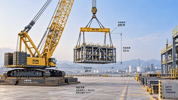
Working radius is the horizontal distance from the crane’s center of rotation to the vertical hoist line. It is not the distance from the nearest crawler track, outrigger, or edge of the crane pad. Confusing these reference points can materially distort a capacity assessment.
Plot the pickup point, travel of the suspended load, and final setting position on a site plan. Check intermediate positions as well as the endpoints. A lift may start comfortably within capacity, then become constrained while slewing around a structure or reaching over a foundation.
Capacity must be read from the chart for the proposed crane configuration. Relevant variables can include boom and jib arrangement, counterweight, reeving, outrigger extension, operating sector, and superlift equipment. Some cranes have structural limits in one part of the chart and stability limits elsewhere. A simple load-times-radius calculation cannot replace the manufacturer’s chart.
Clearance needs a separate geometry check. The hook must reach high enough to accommodate the component, rigging, lifting beam, and setting allowance. At the same time, the boom and suspended load must clear adjacent structures throughout the movement. Loaded boom deflection can affect clearance and operating radius, so a drawing based only on unloaded geometry may be inadequate.
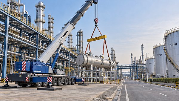
Consider a vessel positioned behind a pipe rack. Moving the crane closer could reduce radius and improve capacity, but that position may place an outrigger above a buried service corridor. Moving farther away may resolve the foundation problem while requiring a different boom arrangement. Crane location, configuration, and ground design must be developed together.
Choose the crane type around the site constraints
Several crane types can perform heavy petrochemical lifting. Their practical differences often emerge in assembly requirements, repositioning, and the space needed around the crane.
A crawler crane can be attractive when repeated lifts justify its mobilization and assembly effort. Its tracks do not guarantee acceptable ground pressure, however. Track loading changes with load position, boom orientation, and configuration. Travel with a suspended load requires a suitable manufacturer-approved configuration and an engineered route.
A telescopic mobile crane may simplify movements between work areas, but its road footprint says little about its operating footprint. Outriggers, counterweight installation, tail swing, support mats, and delivery vehicles all need space. Restricted outrigger extension is usable only where the applicable configuration and chart permit it.
A ring or pedestal system becomes a candidate when conventional arrangements struggle with the required load and reach. Its lifting capability must be weighed against foundation works and installation time. It is most useful when the project can organize major lifts around its established position.
Treat access as a delivery and assembly problem
A crane that fits in the lifting area may still be impossible to mobilize there. Route assessment must cover every major delivery: crane carrier or crawler sections, boom sections, counterweights, mats, and assembly equipment. Transport dimensions and axle or wheel loads can govern access before lifting capacity becomes relevant.
Assess gate widths, turning paths, slopes, overhead restrictions, bridges, culverts, and buried infrastructure. Pavement that accommodates routine plant traffic may not support concentrated crane transport loads. Delivery sequencing also matters: a narrow route can become blocked by components awaiting assembly.
Reserve space for boom assembly, counterweight handling, assist cranes, and component laydown. Include the dismantling sequence. A crane installed early in construction can become trapped when surrounding structures, pipework, or equipment later close its exit route.
In a congested operating plant, improving access may offer more value than increasing crane size. Temporary obstruction removal, a different delivery orientation, or revised module sequencing can reduce radius or simplify setup. Compare these changes against the full cost and operational impact of bringing in a larger crane.
Assess ground support using configuration-specific reactions
Crane mass divided by footprint gives an incomplete picture of ground demand. Outrigger reactions can be highly uneven, and crawler pressures vary as the upper structure slews and the load moves. Obtain reaction or pressure information for the proposed configuration and relevant stages of the lift.
Ground assessment must address both bearing resistance and settlement. A support surface can avoid an obvious bearing failure yet deform enough to affect crane level and load distribution. Backfilled trenches, underground voids, culverts, and changes in soil conditions require particular attention.
Mats spread load only to the extent that their stiffness, strength, arrangement, and supporting ground allow. A larger nominal mat area does not automatically create uniform pressure. The support design should show how reactions pass through the mats into competent ground and how differential settlement is controlled.
Include assembly and dismantling loads in this assessment. Counterweight delivery vehicles and assist cranes may use areas outside the main crane pad. Where loaded travel is proposed, evaluate the full route, including transitions and turning areas, rather than checking only stationary lifting positions.
Account for plant conditions that can change feasibility
Capacity and access checks must reflect the conditions under which the lift will occur. A refinery shutdown may provide only a limited window for delivery, assembly, lifting, and removal. A configuration that takes longer to establish can be commercially unattractive even if its daily rental rate is lower.
Wind assessment should consider the component’s exposed area, shape, orientation, and the crane configuration. A broad module can create significant wind loading despite having a manageable weight. Operating limits must follow the applicable crane instructions and the engineered lift plan; one generic wind-speed threshold cannot cover every load.
Nearby live process equipment introduces additional coordination needs. The lift arrangement should define oversailing restrictions, exclusion areas, permitted crane positions, and interfaces with plant operations. Hazardous-area conditions can also affect equipment suitability and work arrangements.
For tandem lifts, include how load sharing, crane motions, communication, and movement tolerances will be controlled. Small differences in movement can redistribute loads. Compare the complete tandem method with a single-crane alternative, including rigging and coordination demands.
Compare proposals using a common engineering basis
Quotations are meaningful only when suppliers price the same scope. One proposal may include ground mats and assembly cranes, while another assumes the contractor provides them. A lower rental rate can conceal greater civil works, transport costs, or shutdown disruption.
Issue a common enquiry package containing the load register, lifting-point information, site layout, pickup and setting coordinates, required elevations, access restrictions, ground information, and schedule. Ask each supplier to return:
- The proposed crane configuration and applicable load-chart references.
- A lift study showing radius, capacity utilization, and clearances at controlling positions.
- The rigging arrangement, weight deductions, and any main-crane and tailing-crane load cases.
- Ground reactions, support requirements, assembly areas, and transport assumptions.
- Mobilization, assembly, lifting, and dismantling durations, with scope boundaries clearly identified.
Review capacity margin alongside the quality of the inputs. A proposal operating close to its applicable limit leaves less room for changes in weight, radius, or configuration. Acceptable utilization should follow project requirements and the lift’s specific conditions; a single percentage cannot substitute for engineering review.
Compare total installed lifting cost, including transport, temporary works, rigging, assist equipment, standby exposure, and reinstatement. A larger crane may reduce complexity by eliminating a tandem lift. A smaller crane may offer better value if a feasible relocation shortens the radius without creating excessive ground works.
Before awarding the lifting package, resolve the constraint that could invalidate the shortlist: uncertain weight, unavailable crane position, insufficient ground support, or an unworkable assembly route. Once that constraint is established, suppliers can optimize a defined lifting method and provide proposals that are ready for meaningful technical and commercial comparison.
Related News
 Oct 16, 2026Heavy-Duty Petrochemical Lifting: Selecting Cranes by Load, Radius, and Site AccessExplore heavy-duty petrochemical lifting solutions. Compare cranes by load, radius, site access, and ground support to reduce project risk and optimize lifting costs.
 Oct 15, 2026Crane Selection for Petrochemical Turnarounds: Capacity, Radius, and Site AccessExplore petrochemical lifting solutions cranes can deliver, with expert guidance on capacity, working radius, and site access to help you plan a safer, more efficient turnaround.
 Oct 14, 2026High-Capacity Heavy Lifting Solutions: Matching Load, Radius, and Ground ConditionsDiscover heavy lifting solutions high capacity projects demand—compare load charts, working radius, and ground conditions to select a feasible, cost-effective system.
 Oct 13, 2026OEM Equipment Suppliers in Europe: Vetting Quality, Lead Times, and SupportCompare OEM equipment Europe suppliers on quality, lead times, and after-sales support. Discover practical vetting steps to reduce downtime and buy heavy equipment with confidence.

Ms. Elena Rodriguez
Weekly Insights
Stay ahead with our curated technology reports delivered every Monday.