
Selecting TBM Electrical Systems: Power Supply and Tunnel Constraints
Selecting TBM Electrical Systems: Power Supply and Tunnel Constraints
Selecting TBM equipment electrical systems requires more than matching a machine to the available power supply. Project managers must also account for tunnel length, space limitations, ventilation, groundwater and the demands of continuous excavation. An unsuitable configuration can increase downtime, complicate installation and drive up project costs. The most useful selection process therefore starts with the construction plan, not a motor rating in isolation.
The electrical system extends from the utility connection or temporary generation plant to the equipment at the face. Between those points are transformers, switchgear, protection devices, cables, drives and control systems, as well as the pumps, ventilation and material-handling equipment that allow boring to continue. A weakness at any interface can limit a TBM that otherwise appears well suited to the ground.
Start with the actual load, not the installed motor total
The headline power of the cutterhead drive is only part of the demand. A credible load assessment also considers thrust and auxiliary hydraulic systems, screw conveyors or slurry circuits, segment handling, cooling, dewatering, ventilation, lighting and site facilities. The mix changes with the machine type and construction method: an earth pressure balance machine and a slurry TBM do not necessarily place the same demands on their support plant.
Ask the TBM supplier and temporary works designers to prepare a load schedule for each operating state. Normal excavation, cutterhead starting, segment erection, maintenance and recovery after an interruption can produce different combinations of demand. Installed ratings should not simply be added together as though every motor operates at full load simultaneously; equally, assuming generous diversity without evidence can leave the supply undersized.
The assessment should distinguish real power from apparent power and account for power factor, drive losses and anticipated harmonics. A drive may reduce the starting current seen by the supply, but its input characteristics still need to be assessed with the utility and electrical designer. The resulting maximum demand must be checked against the capacity available at the point of connection, including any restrictions imposed by other site users.
Power availability is also a programme question. A utility connection that arrives after TBM assembly can turn a technically sound design into an expensive sequencing problem. Confirm the application process, connection date, responsibility for upstream upgrades and the conditions under which temporary generation might be needed.
Choose the distribution arrangement for the full drive length
As a tunnel advances, the supply route becomes longer. Cable impedance increases voltage drop and losses, while the fault level at the machine can change. A system that performs adequately near the launch shaft may not meet motor, drive or protection requirements at the far end of the drive.
One common design choice is whether to distribute power at a higher voltage and transform it closer to the TBM, rather than carry all major loads over a long low-voltage route. Higher-voltage distribution can reduce current for a given power transfer, potentially easing voltage-drop and cable-size pressures. It also introduces different switchgear, protection, competency and maintenance requirements. The right voltage depends on the load, distance, available equipment and project rules; it should not be selected from tunnel length alone.
Compare arrangements using calculated conditions at launch, intermediate positions and maximum advance. The study should cover cable sizing and thermal limits, voltage drop during relevant operating and starting conditions, short-circuit duties, protective-device coordination and earthing. Where variable-frequency drives are significant, assess harmonic distortion and any utility limits at the connection point. Update the studies when the machine configuration or supply route changes.
Cable handling deserves the same attention as cable calculation. A theoretically suitable cable may be difficult to install around shaft bends, store on a reel, extend safely or protect from moving equipment. The design must account for bending, pulling and reeling limits specified by the cable and equipment suppliers, as well as the practical method for adding cable during advance.
Treat tunnel geometry as an electrical design input
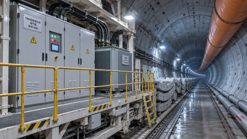
A narrow tunnel does not simply mean smaller cabinets. It changes how components are transported, installed, ventilated and maintained. Space allocated to electrical equipment competes with conveyors, slurry lines, ventilation ducting, walkways, drainage and emergency access. On the backup gantries, every cabinet door, lifting point and maintenance clearance needs to fit within an already crowded envelope.
Location is a trade-off. Placing transformation or distribution equipment closer to the machine can reduce the length of some lower-voltage circuits, but it adds mass and heat underground and may make replacement harder. Keeping more equipment at the surface can simplify access, while increasing the burden on the supply route. Check the arrangement against shaft dimensions, lifting capacity, transport geometry and the heaviest replacement component—not just the original installation plan.
Heat is another constraint that drawings can understate. Transformers, drives and switchgear generate losses, and their cooling performance depends on the conditions where they actually operate. Dust, elevated ambient temperature and restricted airflow can require derating or additional cooling. Electrical and ventilation designers should agree on the heat loads and on what happens if the cooling system is unavailable.
Design for water, dust and a credible fault
Groundwater is not only a civil engineering issue. Water ingress, spray, condensation and contaminated slurry can affect cable joints, connectors, enclosures and insulation. The exposure varies along the tunnel and across the machine, so a single enclosure specification may not be appropriate everywhere. Define the expected environment for each equipment location, then verify protection, drainage, corrosion resistance and inspection arrangements with the supplier.
Protection studies should establish how faults are detected and isolated without unnecessarily disconnecting healthy parts of the system. The design also needs an agreed earthing and bonding arrangement covering the machine, backup equipment and temporary distribution. Applicable electrical, machinery and tunnelling requirements depend on the jurisdiction and project contract; the responsible electrical engineer should confirm them before specifications are frozen.
Do not treat emergency power as a generic spare generator allowance. Identify which functions must remain available or be brought back safely after loss of the main supply. Depending on the project risk assessment, these may include communications, emergency lighting, monitoring, ventilation or dewatering. Establish the required operating duration, transfer method, fuel or battery provision, and testing regime. The arrangement must be coordinated with the tunnel emergency plan rather than assumed to support continued excavation.
Compare electrical options by interruption risk, not purchase price alone
A lower initial equipment price can be offset by cable installation work, utility upgrades, additional cooling or a long wait for a replacement drive. Conversely, adding redundancy everywhere may consume space and budget without addressing the failures that matter most. The useful comparison is between complete, buildable configurations and their consequences for the excavation schedule.
For each option, ask what happens when a transformer, drive module, cooling circuit or communication link fails. Can the fault be diagnosed underground? Can a component be isolated and replaced without dismantling adjacent equipment? Are spares interchangeable, and can they be transported through the shaft and along the backup system? Supplier response time is relevant, but so are local technician competence, diagnostic access and the availability of drawings and software backups.
The answers may change with the drive. A long tunnel with limited access can justify a different spares strategy from a shorter drive with straightforward retrieval. Where the schedule is particularly sensitive to a single component, a project-specific spare or modular replacement strategy may be more valuable than a broad inventory of low-consequence parts.
Close the interfaces before awarding the package
Electrical problems often emerge between contracts: the utility defines one boundary, the TBM supplier another, and the tunnel contractor assumes someone else owns the cable route. Before committing to a configuration, bring those parties together with the ventilation, temporary works and safety teams. A single-line diagram is a useful starting point, but it must be supported by a load schedule, physical layout and operating assumptions.
The procurement review should establish who is responsible for the following items:
- The utility interface, connection studies and any supply-quality limits.
- Transformer and switchgear ratings, fault duties, protection settings and earthing design.
- Cable selection, route, reel or extension method, installation and testing.
- Cooling capacity, environmental protection and access for inspection and replacement.
- Emergency loads, restoration sequence, commissioning tests and operator training.
- Spare parts, diagnostic tools, documentation and support after handover.
Require assumptions to be visible. If the load schedule assumes one ventilation duty, but the tunnel designer later requires another, the effect on transformers, cables and connection capacity should be traceable. The same applies to changes in machine diameter, advance length, muck removal method or groundwater management.
This is where sector intelligence is most useful: connecting machine parameters with construction methods and commercial constraints, rather than treating electrical equipment as a stand-alone purchase. TF-Strategy’s focus on TBM technology and project intelligence reflects that wider decision context. Before final selection, project teams should request a coordinated load study and layout for the maximum planned drive, confirm the supply date and operating limits, and resolve ownership of every critical interface.
Have questions about this sector analysis, or seeking best practices specific to your niche? Drop us a line below and let the senior consultants at TF-Strategy assist you.
Related News
 Nov 19, 2026Selecting TBM Electrical Systems: Power Supply and Tunnel ConstraintsExplore how to select TBM equipment electrical systems for your power supply and tunnel constraints, reduce downtime risks, and make smarter procurement decisions.
 Nov 18, 2026Underground Tunneling Equipment: Types and Uses by Ground ConditionExplore this underground tunneling equipment guide to compare TBMs, roadheaders, and conventional methods by ground condition and choose with confidence.
 Nov 15, 2026Heavy Haulage Equipment for Construction: Choosing by Load and RouteChoose heavy haulage equipment for construction with confidence. Compare load capacity, route restrictions, site access and delivered costs.
 Nov 14, 2026What Is an Equipment Reference Database and What Data Does It Contain?Discover what an equipment reference database contains, from model specifications to source data, and learn how to compare machinery with confidence.

Ms. Elena Rodriguez
Weekly Insights
Stay ahead with our curated technology reports delivered every Monday.