
Underground Tunneling Equipment: Types and Uses by Ground Condition
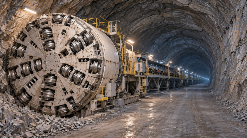
The ground dictates what a tunneling machine must do: cut rock, support loose soil, control groundwater, or handle several of those conditions at once. A hard-rock tunnel boring machine may perform well in competent rock but struggle when the route enters unstable, water-bearing ground. A pressurized machine can control difficult conditions at the face, but its added systems may offer little benefit where the ground is dry and self-supporting.
This underground tunneling equipment guide explains how the main machine types fit different ground conditions and why the excavation system must be considered alongside ground support, muck removal, and site constraints.
Start with the ground along the entire route
Equipment selection begins with the expected ground behavior, not simply a label such as “rock” or “soil.” Rock can be strong and stable, fractured and blocky, or weak enough to deform into an excavation. Soil may stand briefly after excavation or flow into the opening when disturbed. Groundwater can change the behavior of both.
A tunnel may pass through several of these conditions. A machine selected for the longest section still needs a workable plan for fault zones, changes in rock strength, and transitions between soil and rock. The ability to maintain or change cutting tools also matters: abrasive ground can make tool wear a major source of downtime.
These are starting points rather than fixed assignments. Tunnel size, depth, alignment, available site space, and environmental constraints can change the choice.
Hard-rock TBMs: continuous excavation where the ground permits it
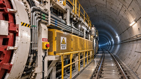
A hard-rock tunnel boring machine uses a rotating cutterhead fitted with disc cutters to fracture rock at the tunnel face. Excavated material passes through the machine to a conveyor, rail system, or another means of transport. TBMs are often considered for long tunnels with a relatively consistent cross-section, where the cost and time involved in assembling and launching the machine can be spread over substantial excavation.
An open hard-rock TBM leaves more of the surrounding rock accessible for inspection and support installation. It can suit competent rock that remains stable long enough for crews to install the required support. When the rock is heavily fractured or prone to collapse, that open configuration can expose the machine and workers to difficult conditions.
Shielded rock TBMs provide a protective structure around part of the machine. Some configurations install precast concrete lining segments behind the cutterhead. A shield can help manage unstable ground, but it does not eliminate the risk of the machine becoming trapped by squeezing ground or falling blocks. The design must account for how the machine will advance, install support, and deal with adverse zones.
Rock strength alone does not predict performance. Fracture patterns influence how rock breaks, while abrasive minerals can accelerate cutter wear. A route with frequent changes in ground condition may require more interventions than its average geological description suggests.
EPB and slurry TBMs: controlling soft ground and water
In loose soil, excavating an unsupported face can cause ground movement to spread toward the surface. This is especially consequential beneath buildings, utilities, roads, or railways. Pressurized TBMs are designed to balance pressure at the face while excavation proceeds, reducing the tendency for soil and groundwater to enter the machine uncontrolled.
Earth pressure balance machines
An earth pressure balance, or EPB, TBM uses excavated soil held in a chamber behind the cutterhead to help support the face. A screw conveyor controls the removal of that material. Operators may add conditioning agents to help the soil flow and maintain suitable behavior inside the chamber.
EPB machines are commonly considered for cohesive soils and some mixed soils when the excavated material can be conditioned effectively. Their suitability depends on more than whether the ground is called clay or sand: permeability, groundwater pressure, particle size, and the presence of boulders all affect the design and operating approach. Coarse, highly permeable ground can make maintaining face pressure more challenging.
Slurry machines
A slurry TBM supports the face with pressurized fluid, often a bentonite-based slurry. Excavated material mixes with the slurry and is pumped to a surface separation plant, where solids are removed and the fluid can be treated for reuse.
This arrangement is often considered for water-bearing, permeable soils such as sands and gravels. It also changes the demands at the surface: the project needs space and equipment for slurry treatment, storage, and disposal of separated material. A machine that is well suited to underground conditions may be difficult to accommodate on a constrained urban site if the surface plant has not been planned.
Both EPB and slurry systems depend on maintaining the intended balance at the face. Neither makes settlement or groundwater movement impossible; performance also depends on ground characterization, machine operation, monitoring, and the response to changing conditions.
Mixed ground: one face, competing demands
A mixed face occurs when the cutterhead encounters materials with different properties at the same time, such as soil above hard rock. The rock needs cutting tools capable of breaking it, while the soil may need pressure support to remain stable. Uneven resistance can also affect cutter wear and how the machine advances.
Mixed-ground TBMs can be configured with cutterheads and operating systems intended to handle a range of materials. Some use interchangeable tools or operating modes, but changing configuration underground can be complex, particularly under groundwater pressure. The range of ground conditions a machine can accommodate is a design question, not a capability to assume from the term “mixed ground.”
For a short transition zone, ground treatment or a localized conventional excavation may be considered as part of the overall plan. For a long route with repeated transitions, the machine’s adaptability and access for maintenance become more central to the decision.
Roadheaders and conventional excavation
Not every underground opening suits a full-face TBM. Stations, junctions, caverns, short tunnels, and tunnels with changing shapes often need a method that can excavate in stages.
A roadheader uses a cutting head mounted on a movable boom to excavate selected portions of the face. It offers flexibility in tunnel shape and can work alongside staged support installation. Roadheaders are commonly used in softer rock and some weak to moderately strong formations, subject to the material’s strength and abrasivity. Very hard or highly abrasive rock can reduce cutting productivity and increase tool consumption.
Drilling and blasting breaks rock with controlled explosives placed in drilled holes. Excavators or loaders then remove the broken material, and crews install support before the next advance. This approach can accommodate changes in tunnel shape and ground conditions, making it a common option for rock tunnels and larger underground spaces. Its suitability depends on factors such as vibration limits, ventilation, access, and the project’s blasting controls.
Excavators and hydraulic breakers can also be used in suitable soil or weak rock, particularly in short sections or larger openings where equipment can maneuver. Where ground is unstable, excavation is usually coordinated closely with support installation; an excavator’s reach does not remove the need to control the exposed face and roof.
The equipment behind the excavation
The machine at the face is only one part of an underground operation. Its practical capacity depends on whether the rest of the system can keep material moving, install support, and provide access for maintenance.
- Ground support equipment: Rock bolting rigs, shotcrete equipment, steel sets, and segment erectors help stabilize the opening. The choice depends on how the ground behaves and when support must be installed.
- Muck removal: Conveyors, rail cars, trucks, or slurry pipelines carry excavated material away. A bottleneck here can stop excavation even when the cutterhead or excavator is ready to work.
- Ventilation and dust control: Fans, ducts, and extraction systems maintain workable conditions, particularly where diesel equipment, dust, blasting fumes, or other airborne hazards are present.
- Water management: Pumps, drainage, and treatment systems handle groundwater and construction water. In some ground, controlling water also helps protect face stability.
- Survey and monitoring: Guidance systems and instruments track alignment, ground movement, and other conditions that inform excavation and support decisions.
These systems compete for space in shafts, tunnels, and surface compounds. A narrow working area can affect equipment access, material delivery, and emergency arrangements as much as it affects the excavation method itself.
How to compare equipment for a specific tunnel
Begin with the geological profile and identify where uncertainty is greatest: fault zones, buried channels, groundwater conditions, or transitions between materials. Consider what happens if the ground behaves differently from the expected profile, including how crews would support the face, access cutting tools, or change the excavation sequence.
Then compare the tunnel layout. A long tunnel with a consistent circular section may favor a TBM, while a short drive with multiple branches or changing dimensions may favor conventional excavation. Launch and retrieval shafts matter too: a large machine needs a way into and out of the ground, plus room for assembly and supporting plant.
Finally, look at the complete construction system. Compare excavation, support, spoil transport, maintenance, surface facilities, and the consequences of interruption together. The most capable cutterhead is of limited value if the project cannot remove spoil quickly enough or install support when the ground requires it.
For early research, the most useful next step is to assemble a route-wide ground profile alongside the tunnel’s dimensions, alignment, groundwater conditions, and surface constraints. That gives equipment suppliers and project teams a common basis for discussing which methods are feasible and where additional investigation would most improve the choice.
Have questions about this sector analysis, or seeking best practices specific to your niche? Drop us a line below and let the senior consultants at TF-Strategy assist you.
Related News
 Nov 18, 2026Underground Tunneling Equipment: Types and Uses by Ground ConditionExplore this underground tunneling equipment guide to compare TBMs, roadheaders, and conventional methods by ground condition and choose with confidence.
 Nov 15, 2026Heavy Haulage Equipment for Construction: Choosing by Load and RouteChoose heavy haulage equipment for construction with confidence. Compare load capacity, route restrictions, site access and delivered costs.
 Nov 14, 2026What Is an Equipment Reference Database and What Data Does It Contain?Discover what an equipment reference database contains, from model specifications to source data, and learn how to compare machinery with confidence.
 Nov 13, 2026Tunnel Boring Machine Safety Certification: What Must Be Verified?Tunnel boring machine safety certification: discover what to verify, from risk assessments and safety systems to site interfaces and commissioning.
Ms. Elena Rodriguez
Weekly Insights
Stay ahead with our curated technology reports delivered every Monday.