
Sizing Industrial Hydraulic Power Packs: Pressure, Flow, and Duty Cycle
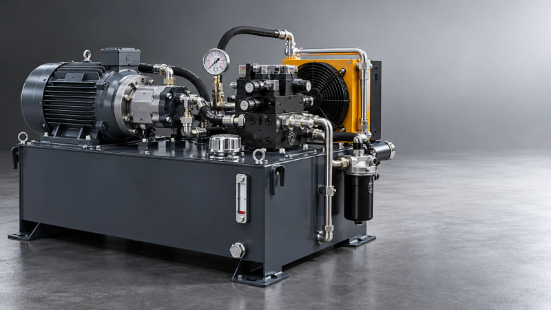
Sizing Industrial Hydraulic Power Packs: Pressure, Flow, and Duty Cycle
Sizing industrial hydraulic power packs requires more than matching a pump to a peak pressure rating. The real task is aligning working pressure, flow demand, and duty cycle with actual load profiles—without buying unnecessary capacity or underestimating heat generation. A unit serving TBM auxiliary circuits, mining maintenance equipment, or lifting machinery may spend more time holding, waiting, or running unloaded than moving its heaviest load. Those operating states belong in the specification.
The most useful starting point is therefore not a supplier’s catalogue. It is a sequence of machine operations, with enough detail to show which functions overlap, how long each lasts, and what happens when the operator interrupts the cycle.
Build the load profile before selecting hardware
For each actuator, record required force or torque, travel speed, stroke or rotation, operating duration, and load direction. Add the expected ambient temperature, installation altitude, fluid requirements, and available electrical supply. Distinguish normal production from setup, maintenance, emergency recovery, and foreseeable stalled conditions.
A TBM auxiliary circuit illustrates the problem. A clamp may need substantial pressure while barely moving, while a positioning cylinder needs more flow at a lower load. Simply combining the highest pressure and highest flow can create a duty point the machine never actually uses. Conversely, assuming these functions always operate separately can leave the pack short of capacity when the control sequence permits overlap.
This connection between machinery parameters and construction methodology is central to TF-Strategy’s heavy-equipment analysis. The same hydraulic hardware can face very different demands depending on the operating sequence, site constraints, and recovery procedures. Specify those conditions before asking suppliers to price alternatives.
Pressure comes from the load—not the pump label
For a cylinder, the basic relationship is force = pressure difference × effective piston area. Use the correct area for the direction of travel: retraction acts on the annular area, not the full bore. Where return pressure is significant, calculate forces on both sides of the piston rather than treating the return line as pressure-free.
The pump must supply the required actuator pressure plus losses through piping, hoses, filters, valves, and manifolds along the active flow path. Those losses change with flow and viscosity. A circuit that performs adequately with warm oil may respond poorly during a cold start, particularly where long lines or restrictive fittings are involved.
Keep normal working pressure, relief setting, and component pressure ratings separate. The relief valve protects against excessive pressure; it should not be the routine means of regulating a continuously operating circuit. Pressure spikes also require attention. Abrupt valve switching, stopped loads, and trapped fluid can create local peaks that a slowly sampled pressure gauge will miss.
There is no universal percentage that makes a pressure margin correct. Allowance should reflect load uncertainty, control behaviour, transient analysis, and component limits. Increasing pressure indiscriminately can force a change in pumps, seals, hoses, and valve ratings without improving useful machine performance.
Flow determines speed, but simultaneous demand decides capacity
Cylinder flow follows Q = A × v, using consistent units. Hydraulic motor demand depends on displacement, rotational speed, and volumetric efficiency. Calculate these requirements at the actuator, then account for pump leakage and any continuous control or flushing flows. Check supplier performance data at the intended pressure, speed, fluid viscosity, and temperature—not just nominal displacement.
For shared supplies, add the flows that genuinely occur together. Do not add every installed actuator’s maximum flow unless the machine must deliver that operating state. Equally, do not apply a convenient diversity factor without validating the control sequence.
Pressure mismatch is an easily missed source of waste. If one actuator needs high pressure while another needs high flow at low pressure, a common supply may throttle away substantial energy in the lower-pressure branch. Separate pump sections, staged high-low circuits, or load-sensing arrangements may be worth evaluating. The right answer depends on how often that mismatch occurs; extra complexity is difficult to justify for an occasional short movement.
Return flow needs its own calculation. During cylinder retraction, cap-end discharge can exceed pump delivery because of the area ratio. Undersized return filters, valves, or lines can then produce backpressure that reduces force, increases heating, and changes motion behaviour.
Translate the operating cycle into motor and pump requirements
For pressure in bar and flow in litres per minute, hydraulic output power is:
Phydraulic (kW) = p × Q ÷ 600
Pump shaft power is higher because the pump is not perfectly efficient. Divide hydraulic output by the applicable pump efficiency. Electrical input is higher again once motor and drive losses are included. Keep those boundaries clear when comparing quotations: “power consumption” and “motor rating” are not interchangeable.
As an illustrative calculation, 200 bar at 60 L/min produces 20 kW of hydraulic output. At an assumed pump overall efficiency of 0.85, shaft demand is approximately 23.5 kW. These are calculation assumptions, not recommended equipment ratings. Motor selection still requires the actual operating envelope, starting method, overload capability, and site derating.
A useful cycle sheet might contain the following states. Its purpose is to reveal different sizing constraints, not merely calculate one average power figure.
A motor cannot be selected from time-averaged hydraulic power alone. Short high-torque events may exceed its capability even when average energy demand appears modest. Have the motor supplier verify the load cycle, starts per hour, acceleration, drive limits, and cooling conditions. Low-speed operation with a variable-frequency drive deserves particular attention where the motor relies on a shaft-mounted fan.
Fixed-displacement pumps can be appropriate for predictable, intermittent work with effective unloading. Variable-displacement pumps become attractive where demand changes frequently or pressure must remain available during long pauses. Neither architecture is automatically more economical: evaluate purchase cost, controls, standby losses, repair capability, and contamination sensitivity together.
Heat balance often sets the practical limit
Hydraulic losses become heat. Pump inefficiency, throttling, internal leakage, and pressure drops all contribute. Continuous relief flow is especially costly: bypassing 20 L/min at 200 bar converts approximately 6.7 kW into heat at the relief path alone. That calculation excludes additional pump and motor losses.
Estimate heat generation across the operating cycle, then compare it with heat rejection at the worst credible ambient condition. Do not select an oil cooler solely from its headline kilowatt rating. Capacity depends on oil-to-air or oil-to-water temperature difference, fluid flow, airflow, and installation conditions. A cooler drawing warm recirculated enclosure air will not perform like the same unit supplied with unobstructed ambient air.
Reservoir volume cannot be settled by a universal “multiples of pump flow” rule. The tank must accommodate changing cylinder inventory, drainback, thermal expansion, adequate pump inlet submergence, and space for air release. Internal layout matters: poorly positioned returns can send aerated oil straight back to the suction connection.
A larger reservoir slows temperature rise but does not necessarily solve an inadequate steady-state heat balance. In a confined tunnel installation, cooler access and ventilation may matter more than extra tank capacity. At an exposed mine site, cold-start viscosity, dust loading, and cooler cleaning access can become decisive.
Check the conditions hidden behind the headline ratings
Pump inlet conditions deserve a separate review. Cold oil, restricted strainers, long suction lines, and reduced atmospheric pressure at altitude can reduce the available inlet-pressure margin. Verify the pump manufacturer’s limits throughout startup and normal operation. An inlet restriction is not cured by specifying a larger electric motor.
For filtration, define the cleanliness required by the most sensitive components and how it will be maintained during servicing. Compare filter pressure drop at cold viscosity as well as warm operation. Consider element replacement access, bypass behaviour, condition indication, and the contamination introduced when hoses or actuators are changed underground or in a workshop.
Accumulators can supply brief flow peaks or support specific emergency functions, but they do not eliminate the energy requirement. Recharge time, usable oil volume across the permitted pressure range, precharge, temperature, and isolation arrangements all need calculation. Lifting systems also require an appropriate load-holding strategy; pump pressure alone is not a safe means of retaining a suspended load.
Compare proposals against the same operating envelope
When evaluating industrial hydraulic power packs, ask suppliers to show achievable pressure and flow together, expected shaft demand, cycle assumptions, thermal calculations, and any operating restrictions. Require them to identify whether quoted efficiency represents a single favourable point or the expected working range.
Acceptance testing should follow the intended sequence: cold startup, overlapping functions, loaded motion, holding, and sustained operation sufficient to assess temperature stability. Record pressure, flow, electrical input, oil temperature, and ambient conditions. Establish measurement points and acceptance limits before the test, including how abnormal pressure peaks will be captured.
The better-sized pack is not necessarily the smallest or the most powerful. It is the one whose margins can be explained: enough pressure for the real load, enough flow for the permitted movements, and enough thermal capacity for the actual working day. If a proposal cannot connect those three requirements to a documented cycle, its nameplate ratings are not yet a sufficient basis for selection.
Related News
 Oct 19, 2026Sizing Industrial Hydraulic Power Packs: Pressure, Flow, and Duty CycleSize industrial hydraulic power packs with confidence. Learn how pressure, flow, and duty cycle affect performance, energy costs, and heat control—and avoid costly sizing mistakes.
 Oct 18, 2026How Equipment Specifications Affect Purchase, Installation, and Operating CostsExplore equipment specification planning cost factors that shape purchase, installation, and operating budgets. Compare lifecycle costs, avoid oversizing, and buy with confidence.
 Oct 17, 2026Tunnel Boring Machine Supplier List: Compare TBM Types and Service CoverageExplore our tunnel boring machinery supplier list to compare EPB, slurry and hard rock TBMs, assess service coverage and lifecycle costs, and build a smarter procurement shortlist.
 Oct 16, 2026Heavy-Duty Petrochemical Lifting: Selecting Cranes by Load, Radius, and Site AccessExplore heavy-duty petrochemical lifting solutions. Compare cranes by load, radius, site access, and ground support to reduce project risk and optimize lifting costs.

Ms. Elena Rodriguez
Weekly Insights
Stay ahead with our curated technology reports delivered every Monday.