
TBM Electrical Systems: Troubleshooting Ground Faults in Tunneling
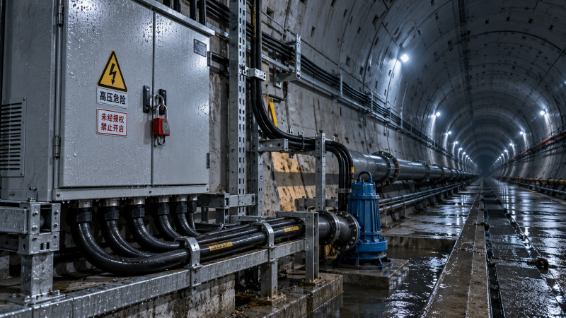
A ground-fault alarm during excavation can stop a drive, interrupt auxiliary equipment, or leave a machine operating with degraded insulation. Resetting the protection without finding the affected circuit risks another trip and may expose damaged equipment or personnel to electrical danger.
The practical response is to preserve the alarm information, establish the electrical system configuration, and isolate the fault to a feeder or load before testing components. In TBM equipment electrical systems, moisture, cable movement, contaminated enclosures, and deteriorated motor insulation are frequent investigation points, but the location indicated by an alarm is not always the physical location of the defect.
Start with the event, not the reset button
Record the exact alarm or trip message, the protective device that operated, and whether the fault occurred at startup, during steady operation, or after a particular load was switched on. Save relay event records and insulation-monitoring trends where available. A fault that appears when a pump starts calls for a different investigation from an alarm that develops gradually while several circuits remain energized.
Check the drawings against the actual machine configuration. Temporary power arrangements, trailing cables, ventilation equipment, pumps, and recently connected service loads can change the fault path. Identify the supply source, transformer connections, grounding arrangement, protective zones, and any insulation monitoring device before deciding what a reading means.
A ground fault is not always a direct short to the machine frame. It can be a partial insulation breakdown or leakage through water and contamination. On an unearthed or impedance-grounded system, the first fault may produce an alarm rather than an immediate trip, depending on the protection design. A second fault can create a more serious condition, so an alarm should not be treated as permission to continue normal operation without following the site’s response procedure.
Make the affected section safe to investigate
Electrical troubleshooting should be performed by authorized personnel under the site’s electrical safety and lockout procedures. Stop the relevant equipment, isolate all identified sources, apply lockout and tagout, and verify absence of voltage using an appropriately rated and proven test instrument. Establish the required protective measures for the voltage and available fault energy.
Do not assume that opening one disconnect makes a TBM circuit safe. Possible sources include the main supply, auxiliary transformers, generators, uninterruptible power supplies, control power, regenerative drives, and backfeeds from interconnected equipment. Variable-frequency drive DC links and other capacitive components can retain hazardous energy after isolation. Follow the manufacturer’s discharge and verification instructions; waiting for an indicator to go out is not a substitute for the specified voltage check.
Before disconnecting protective conductors, shields, or equipotential bonds for a test, assess the consequences and follow an approved procedure. Never defeat a protective function or remove a ground connection merely to clear an alarm. Work in wet or confined tunnel areas may also require coordination with ventilation, access control, and other site activities.
Use the alarm pattern to narrow the search
These patterns guide the search; they do not prove a cause. Leakage from multiple healthy-looking branches may combine, and a fault on one circuit can influence a common monitor. Equally, a protection trip can reflect an incorrect connection or sensor problem. Verify the protection scheme and test evidence before replacing equipment.
Separate the faulted section
- Define the protected area. Use the single-line diagram and device documentation to determine which feeders and components are inside the tripped relay’s or monitor’s sensing zone. Note any circuits that remain connected despite their local switches being open.
- Inspect before testing. With the equipment safely isolated, look for standing water, damaged glands, conductive deposits, loose connections, heat damage, and cable sheath injuries. Photograph and label suspect locations without disturbing evidence unnecessarily.
- Divide the circuit. Isolate downstream branches using the approved switching and lockout plan. Record the position of each device and the equipment disconnected. Where the protection design permits controlled re-energization, restore only the sections needed to determine whether the alarm returns; keep personnel clear and maintain normal protective functions.
- Test the isolated suspect section. Apply the appropriate manufacturer-approved insulation and continuity tests to distinguish a cable problem from a motor, heater, junction box, or other connected load. Compare results with equipment instructions and relevant previous readings, not with an assumed universal pass value.
- Confirm the repair location. A low reading on a feeder with multiple connected loads identifies a suspect section, not necessarily a bad cable. Disconnect further at accessible, approved boundaries and repeat the suitable test until the defective portion is identified.
Where the fault is intermittent, preserve the conditions associated with the alarm in the work record: machine position, recent water ingress, operating load, and whether the fault followed a particular switching action. Do not manipulate an energized cable to provoke a fault. An intermittent defect may require an extended inspection or a controlled test plan developed with the site’s electrical authority and equipment manufacturer.
Choose tests that the connected equipment can withstand
An insulation resistance tester can help locate a ground fault on an isolated cable or winding, but its test voltage can damage sensitive electronics. Drives, surge protection devices, filters, monitoring equipment, sensors, and control modules may need to be disconnected or otherwise handled in accordance with their instructions. Verify the circuit is isolated and discharged, confirm exactly what remains connected, and use the test voltage and duration specified for that equipment.
Test results are affected by cable length, temperature, humidity, contamination, and the number of connected loads. Record the test voltage, duration, temperature where relevant, circuit configuration, and readings. A comparison is useful only when the earlier measurement was made under sufficiently similar conditions. Discharge tested components safely after the test and verify their condition before touching or reconnecting them.
On variable-frequency drive circuits, filters and cable capacitance can produce earth leakage during normal operation. Protective devices and monitoring systems must be compatible with the drive and grounding arrangement. Do not increase a trip threshold or bypass a filter simply because a drive starts: first determine whether the measured behavior is expected and whether the settings match the approved coordination study and manufacturer’s instructions.
Inspect the places a TBM puts under stress
Cables and terminations
Follow the suspect cable through moving sections, cable reels, drag chains, bulkheads, and points where it passes near sharp steelwork. External sheath damage can allow water to enter even when the conductor insulation is not visibly exposed. Check for flattened sections, excessive bending, damaged supports, and signs that a cable has rubbed against adjacent equipment.
At terminations, inspect gland sealing, strain relief, moisture tracks, and conductor insulation. A clean exterior does not prove that the inside of a junction box is dry. Open enclosures only after isolation and environmental controls are in place; avoid introducing further contamination while inspecting them.
Motors, pumps, and wet enclosures
Pump motors and associated cables deserve attention where water, slurry, or washdown can reach connectors and terminal boxes. Separate the motor from its supply cable when the equipment design permits, then test each portion according to its instructions. This prevents a damaged cable from being mistaken for a failed winding, or vice versa.
Condensation and conductive dust can create surface leakage in cabinets. Inspect seals, drains, space heaters, ventilation paths, and evidence of water entry. Drying or cleaning may restore insulation temporarily, but the source of ingress must also be corrected. Use cleaning and drying methods approved for the components; heat, solvents, or compressed air applied indiscriminately can cause additional damage.
Protective and monitoring circuits
Check current-transformer orientation, the route of conductors through a residual-current sensor, relay supply, wiring, and settings against the approved schematic. An incorrectly routed neutral or parallel return path can distort a residual-current measurement. On an insulation-monitored system, verify that the monitor and its connections suit the network configuration and that other connected devices are not interfering with its operation.
These checks do not justify declaring a protection device faulty merely because a visual inspection finds no damage. Functional testing, injection testing, and setting changes should follow the device documentation and site authorization requirements.
Return the machine to service with evidence
Repair or replace the defective component using parts and methods approved for the application. Restore cable support, sealing, segregation, and protective bonding as specified. Remove temporary test connections, reconnect disconnected electronics and surge protection, and independently verify that all earth connections and covers are restored before energization.
Document the original alarm, isolated section, test conditions, readings, repair, and final configuration. Complete the required electrical and protection checks, then energize in the sequence authorized by the site. Observe the relevant monitor or relay and run the affected equipment under controlled conditions. A single successful reset is not proof that an intermittent fault has been eliminated; compare subsequent readings and operating behavior with the recorded fault pattern.
Escalate when the fault cannot be isolated without exposing personnel to energized parts, when protection coordination is uncertain, or when repeated trips continue after a verified repair. Preserving event records and comparable test results gives the responsible electrical engineer or equipment manufacturer a firmer basis for the next diagnostic step.
Have questions about this sector analysis, or seeking best practices specific to your niche? Drop us a line below and let the senior consultants at TF-Strategy assist you.
Related News
 Nov 01, 2026TBM Electrical Systems: Troubleshooting Ground Faults in TunnelingTroubleshoot ground faults in TBM equipment electrical systems with practical guidance on safe isolation, testing, repairs, and reliable return to service.
 Oct 31, 2026Product Application Guidance: Matching Products to Operating ConditionsProduct application guidance for matching heavy equipment to site conditions, improving safety, productivity, and total cost decisions. Explore the practical guide.
 Oct 30, 2026Selecting Mining Equipment for Extreme Heat in the Middle EastChoosing extreme temperature mining equipment Middle East sites can rely on? Compare cooling, dust protection and lifecycle costs to make a confident choice.
 Oct 28, 2026Choosing a Heavy Equipment Market Intelligence Database: Coverage and Data QualityChoosing a heavy equipment market intelligence database? Compare coverage, data quality, source transparency, and updates to find reliable insights for smarter commercial decisions.



Ms. Elena Rodriguez
Weekly Insights
Stay ahead with our curated technology reports delivered every Monday.