
Predictive Maintenance for Tunneling Equipment: Sensors That Detect Wear
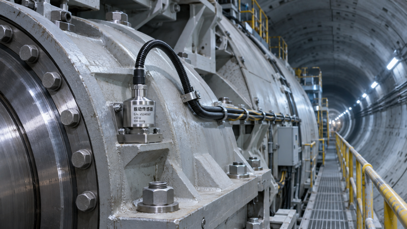
Wear monitoring on a tunnel boring machine (TBM) works best when sensor readings are compared with the machine’s operating condition. Rising vibration at a main bearing, for example, is more meaningful when it persists at similar cutterhead speed and thrust than when it appears only during a change in ground. Temperature, hydraulic pressure, oil condition and acoustic signals add evidence, but each measurement has limits: a sensor usually detects a change in component behavior rather than measuring the remaining material directly.
A useful predictive maintenance arrangement links those signals to cutterhead position, operating hours, advance rate, geology and maintenance records. The result is a way to distinguish a developing fault from a temporary load change and to decide when inspection is warranted.
Cutter wear: separate ground response from tool condition
Disc cutters wear through contact with rock, but their response is inseparable from the ground being excavated. Hardness, abrasiveness, fractures and transitions between formations all change the forces on the cutterhead. Thrust, torque, rotation speed and penetration per revolution therefore provide context for wear assessment, even when none of them measures an individual cutter’s condition.
A sustained change in torque or thrust at comparable penetration and ground conditions can justify closer investigation. Yet a rise in thrust alone does not establish that cutters are worn: a harder rock layer, reduced cutterhead speed or a change in machine steering can produce a similar pattern. Conversely, averaging values over an entire shift can hide a localized problem that appears only during part of each revolution.
Where instrumentation supports it, cutterhead position can be synchronized with load and vibration measurements. A recurring disturbance at the same angular position is useful evidence of a localized issue, such as a damaged cutter or an obstruction. Structural resonances and sensor mounting faults can also repeat with rotation, so the signal needs confirmation against operating history and, when access is safe, physical inspection.
Direct and indirect wear measurements
Direct wear indicators, where fitted to cutter assemblies, can report a defined wear condition closer to the cutting tool. Their value depends on where the indicator is placed, whether it survives the cutting environment and whether it represents the wear mode of concern. A single indicator may not describe uneven wear around a cutter ring or identify every bearing failure inside the cutter.
Indirect methods use changes in vibration, acoustic emissions or machine loads to identify abnormal behavior. They are easier to relate to components that cannot be inspected continuously, but they require a baseline and a means of separating cutter signals from the much larger response of the machine. A flat spot on a cutter, for instance, can create a repeated impact; similar impacts can also come from joints, debris or other rotating parts.
Inspection records give the data a physical reference. Record cutter location, remaining profile or measured dimensions, visible damage and the ground excavated since the previous inspection. Replacing or relocating a cutter changes the interpretation of its history, so the monitoring record should follow the component as well as its position.
Bearing vibration and temperature: read the trend together
Main bearing and gearbox condition monitoring commonly combines vibration with temperature and lubrication data. Accelerometers mounted on a bearing housing or gearbox casing pick up mechanical movement transmitted through the structure. A loose mounting, thick coating, damaged cable or altered sensor position can change the reading without any change in the bearing itself.
Vibration amplitude is useful for screening, but a single overall value can conceal the source of a fault. Frequency analysis and, where suitable, envelope analysis can reveal repeated impacts associated with rolling-element damage. Interpretation must account for shaft speed, gearing, load and the transmission path from the defect to the sensor. Slow rotation and heavy background noise can make early bearing faults difficult to isolate; a clean-looking spectrum does not prove the bearing is healthy.
Temperature responds to friction, heat transfer and the surrounding environment. A rising bearing housing temperature accompanied by worsening vibration or abnormal lubricant condition is more persuasive than a temperature rise alone. Oil temperature, cooling performance, ambient temperature and the time since startup all affect the reading. Compare like operating periods and locate the temperature sensor consistently; housing temperature is not necessarily the temperature at the contact surface.
Trend direction matters: a stable value near a locally established limit and a rapidly rising value below that limit call for different attention. Alarm settings should reflect the component supplier’s guidance, the installation and observed behavior. A generic vibration or temperature threshold cannot be assumed to fit every TBM bearing.
Hydraulic pressure and oil condition
Hydraulic systems carry thrust, steering and auxiliary functions through pumps, valves, cylinders and hoses. Pressure transducers show the load in a circuit, while flow, oil temperature and reservoir level provide context. Pressure by itself does not identify wear: a high reading can reflect increased external resistance, a restriction, a control setting or a component fault.
Internal leakage in a pump or cylinder can appear as slower movement or reduced ability to hold position, particularly as oil warms and viscosity falls. Similar symptoms can arise from valve leakage or a control problem. Comparing pressure with commanded movement, actual cylinder movement and oil temperature helps narrow the fault before components are removed.
Oil sampling and online particle or moisture sensors add another view of deterioration. A rising particle count points to contamination, but it does not automatically identify the component producing it. Sampling location, operating state and recent oil or filter changes affect the result. Laboratory analysis of a representative sample, combined with filter inspection and maintenance history, helps distinguish external contamination from internal wear.
Water ingress deserves particular attention underground because it can affect lubrication and accelerate corrosion. A moisture reading should be interpreted against the fluid type, temperature and sensor method. Follow the equipment and lubricant guidance for response limits, and investigate the ingress path rather than treating repeated oil replacement as a complete repair.
Acoustic signals need a clear source
Acoustic emission sensors detect high-frequency energy released by events such as impacts, friction and crack-related activity. They can add sensitivity to a condition-monitoring system, especially when conventional low-frequency vibration is obscured. Their useful range and interpretation are strongly affected by the mounting surface and the material between the source and sensor.
On a TBM, cutting action, hydraulic equipment, pumps and loose structures all generate noise. An acoustic event becomes more useful when its timing corresponds to a known component cycle or when it is supported by another measurement. A sudden increase during excavation alone is insufficient evidence to replace a cutter or bearing. A persistent increase during comparable operation, supported by changes in load, vibration or inspection findings, provides a stronger basis for intervention.
Sensor coupling also matters. A poorly bonded or loosened acoustic sensor can lose sensitivity or introduce inconsistent readings. After installation or maintenance, document the mounting location and method and verify that the channel responds as expected. Do not compare signals from different mounting arrangements as though they were identical.
Build a baseline that follows the operating state
A baseline is a record of normal behavior under defined conditions, not a single value captured at commissioning. A TBM has distinct states: excavation, thrust without advance, startup, shutdown, stopped rotation and maintenance testing. Mixing them in one average creates misleading trends. Separate records by state and retain the variables needed to compare similar periods, including speed, load, temperature and ground description where available.
Time alignment is just as important as sensor selection. If vibration, pressure and machine-control data have inconsistent timestamps, a real event may appear unrelated to the load change that caused it. Confirm clock synchronization and preserve enough time resolution for the fault being investigated. A slowly sampled temperature trend can be useful for heating; it cannot reconstruct a short impact that was never captured.
Data quality needs its own indicators. Missing samples, a frozen value, saturation, electrical interference or an intermittent cable can resemble a mechanical fault or hide one. Record sensor replacements, calibration and changes to filtering or acquisition settings. After such a change, assess whether the previous baseline remains comparable before interpreting a step change as wear.
Turn an alert into a maintenance decision
An alert should identify the affected component, the signal that changed and the operating conditions associated with the change. It is more useful when it includes the trend over time and related evidence: for example, bearing vibration at comparable speed, housing temperature, lubricant condition and the date of the last relevant service.
Start by establishing whether the machine was in a comparable state and whether the sensor channel is credible. Then look for independent evidence. A vibration increase with normal temperature and clean oil may justify closer monitoring and investigation of mounting or load changes. A continuing increase accompanied by heat, abnormal oil debris or repeated impacts warrants a more urgent assessment under the equipment’s maintenance procedures.
When a fault is suspected, use the available evidence to define the next action: inspect at the next planned access opportunity, collect an oil sample, verify a sensor, adjust the monitoring interval or stop equipment in accordance with site procedures. Access to the cutterhead or excavation chamber requires the applicable isolation and ground-control arrangements; a prediction does not establish that entry is safe.
After inspection or repair, record the finding even if no defect was found. Document the component, observed condition, action taken and subsequent sensor response. These records make future alerts more useful, while exposing patterns that were caused by geology, operating changes or instrumentation rather than wear.
Have questions about this sector analysis, or seeking best practices specific to your niche? Drop us a line below and let the senior consultants at TF-Strategy assist you.
Related News
 Nov 12, 2026Predictive Maintenance for Tunneling Equipment: Sensors That Detect WearExplore tunneling equipment innovations predictive maintenance teams use to detect wear, interpret sensor trends and plan timely TBM inspections.
 Nov 04, 2026Mining Industry Developments: Automation, Electrification and Operating CostsExplore mining industry developments in automation and electrification, and learn how to evaluate fleet investments, productivity and operating costs.
 Oct 29, 2026Middle East Heavy Haulage Equipment Market: Energy and Infrastructure DemandExplore the heavy haulage equipment Middle East market for energy and infrastructure demand, route challenges, and fleet investment insights to make smarter buying decisions.
 Oct 15, 2026Mining Truck Maintenance Markets: Service Models Reshaping Fleet AvailabilityMining truck fleet maintenance and repair services market: discover service models, predictive insights, and strategies to maximize fleet availability.



Prof. Marcus Chen
Weekly Insights
Stay ahead with our curated technology reports delivered every Monday.