
Crawler Crane Application Analysis for Wind Farms, Bridges, and Confined Sites
Choosing the Crane Starts with the Lift Path, Not the Rated Capacity
A crawler crane can be the right primary lifting machine for wind farms, bridge works, and constrained sites, but only when its full operating envelope matches the project. Rated capacity alone is a weak selection tool. A crane that can lift the component at a short radius may still be unsuitable once boom length, working radius, hook height, ground bearing capacity, transport restrictions, assembly space, and weather windows are considered.
For project leaders, the useful question is not “What tonnage crane do we need?” It is: “Can this crane complete each critical lift safely, repeatedly, and without creating a schedule bottleneck?” That question produces different answers for a wind turbine erection package, a bridge girder installation, and a lift inside a dense industrial or urban work zone.
A sound crawler crane application analysis therefore begins with the heaviest and most demanding lift, then checks whether the same configuration can work through the remaining sequence with acceptable mobilization effort and site preparation. In many projects, the most expensive crane on site is not the largest machine. It is the machine selected for one theoretical lift case that cannot be efficiently deployed across the actual workfront.
Wind Farms: Capacity Must Be Evaluated Against Height, Radius, and Repetition
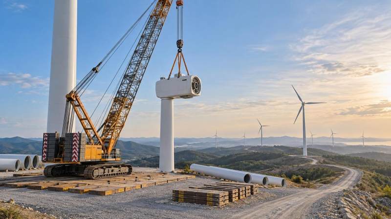
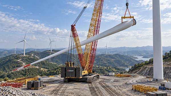
Wind farm construction is often associated with very large crawler cranes because nacelles, tower sections, hubs, and blades require substantial lifting capability at height. Yet the crane selection problem is more specific than component weight. The governing case may be the nacelle lift at the required hub height, a blade installation with a large projected area, or a lift performed from a restricted crane position because roads, foundations, cable trenches, or terrain prevent the ideal setup.
The first assessment should establish the actual lift geometry for every turbine model and every available crane location. This includes the component weight with lifting gear, boom and jib configuration, operating radius, required hook height, allowable slew range, and any need for tailing or auxiliary lifting. Capacity charts must be read for the intended configuration, including counterweight, carbody counterweight where applicable, track position, mast arrangement, and luffing-jib combination. A capacity figure taken from a brochure or from a different boom mode is not sufficient for a construction decision.
Wind projects also expose a common misconception: that crawler mobility automatically makes relocation simple. Crawlers can travel around a prepared work area with load-dependent restrictions, but moving between turbine positions is often a civil and logistics exercise. Site roads must support crane transport components, delivery vehicles, and sometimes the assembled crane itself. Gradients, turning radii, culverts, soft shoulders, overhead services, and turbine foundation exclusion zones can govern the crane plan as much as the lift chart.
Ground pressure deserves early attention. Crane mats may distribute load, but they do not correct a weak or poorly drained subgrade. Wind farm sites frequently involve agricultural land, reclaimed ground, slopes, or seasonal moisture changes. The crane’s maximum ground bearing demand is not always limited to the vertical lift phase. Assembly, counterweight installation, boom handling, slew operations, and travel can create separate loading conditions. The lift plan should identify each of these conditions rather than relying on one generic bearing-pressure calculation.
Weather is another operational constraint that can reshape the equipment decision. Tall components and long blades are sensitive to wind, while visibility, lightning procedures, icing, and ground saturation may also interrupt work. The crane can be technically capable and still spend critical days unavailable for lifting. Projects with narrow commissioning windows benefit from evaluating how quickly the crane can resume work after a weather hold, whether it can serve multiple turbine positions without major reconfiguration, and whether a backup lifting strategy is needed for schedule-critical components.
For wind farms, a larger crane may be justified when it reduces boom changes, improves operating radius flexibility, or allows a more efficient sequence across several turbine locations. It is less justified when the additional crane size creates transport, assembly, road-upgrade, or ground-improvement work that overwhelms the productivity benefit. The appropriate configuration is usually the one that gives a reasonable margin on the critical lift while fitting the project’s access and repetition pattern.
Bridge Construction: The Lift Is Part of the Structural Sequence
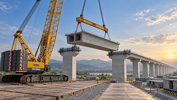
Bridge work demands a different perspective because the lifted item is often part of an incomplete structure. Precast girders, steel segments, pier caps, temporary works, launching equipment, and reinforcement assemblies may all require crawler crane support, but the crane operation cannot be separated from structural stability and traffic management.
The basic lift calculation remains important, yet the workfront creates additional questions. Where can the crane stand without overloading a temporary deck, embankment, approach slab, or partially completed pier area? Can it slew the girder into position without passing over live traffic, rail infrastructure, water, or adjacent property? Does the final placement require the crane to work at a different radius from the initial pick? These details often determine whether a single crawler crane is practical or whether a different lifting method, tandem lift, temporary trestle, or staged installation is more suitable.
Bridge girder installation illustrates why the pick weight alone can mislead. Long girders can be relatively light compared with their length, but they introduce control issues: deflection, rotation, lifting-point tolerances, wind exposure, and limited clearance near piers or overhead structures. Where two cranes are used, the operation becomes more complex than two separate capacity checks. Load sharing, synchronized movements, communication protocol, travel limits, and contingency actions must be defined for the whole lift. Small differences in hoist speed or crane position can alter loads during rotation and placement.
A crawler crane is often attractive on bridge projects because its tracks provide a stable base and it can be configured with long boom combinations. However, track stability does not eliminate the need to assess the supporting surface. Working near excavations, riverbanks, abutments, retaining walls, or temporary fills introduces settlement and edge-distance risks. Crane mats can protect the surface and spread bearing pressure, but the engineering review must consider the full support system beneath them.
Traffic and possession windows frequently affect crane utilization. A crane may have only a limited overnight or weekend period to install a critical element above a road or rail corridor. In that situation, choosing a machine with marginal capacity or a slow configuration change can turn a planned closure into a high-risk event. The crane plan should account for pre-lift assembly, pre-rigging, exclusion-zone setup, access verification, lift execution, and post-lift release of the corridor. The available lifting window is always shorter than the nominal closure period.
For bridge managers, the practical selection test is whether the crane supports the structural sequence without forcing risky compromises in staging. A machine that performs a girder lift well but blocks pier works, limits material deliveries, or requires repeated dismantling may increase overall project duration. Crane positioning should be coordinated with formwork, temporary supports, concrete pours, haul routes, and the next construction phase before mobilization is finalized.
Confined Sites: Maneuvering Space Can Be More Important Than Tonnage
In refineries, power plants, urban sites, industrial expansions, and tight marine facilities, crawler crane selection is often driven by access and geometry rather than maximum load. The work may involve vessels, modules, heat exchangers, pipe racks, precast elements, or plant equipment, but the shared challenge is limited room for assembly, slewing, tail swing, boom movement, and transport delivery.
A crawler crane can offer useful low-speed mobility once erected, yet it needs a defined physical envelope. The team should map the crane’s tail swing, boom clearance, counterweight installation area, track travel path, outrigger-free operating footprint, and assembly crane requirements. A location that appears adequate for the final lift may not have enough room to build the main boom, install counterweights, or remove the machine after work is complete.
Vertical constraints can be equally restrictive. Overhead pipe racks, energized lines, process structures, tower cranes, adjacent buildings, and temporary roofs can block boom movement even where the load path appears clear. The lift study should trace the hook and load through the complete operation: pick, hoist, slew, boom movement, travel if applicable, set-down, and hook release. A collision review limited to the final placement location is incomplete.
Confined-site projects also benefit from distinguishing between a crane that can physically enter the site and a crane that can work productively there. A smaller crawler crane may have lower headline capacity but offer better access, shorter assembly time, less demanding ground preparation, and reduced interference with other trades. Conversely, using several small lifts or frequent equipment changes to avoid mobilizing a larger crane can create more handling operations, each with its own exposure. The right decision depends on the number of lifts, their timing, and the penalty of disrupting the wider site.
Where work is close to operating assets, lifting controls need to be matched to the site’s risk environment. Restricted slew zones, height limits, load-path exclusions, anti-two-block devices, wind monitoring, clear signaling arrangements, and lift supervision are established controls, but their effectiveness depends on disciplined setup and verification. The project team should also agree in advance on stop-work triggers, especially where changing plant conditions, restricted visibility, or simultaneous operations can affect the lift.
A Practical Selection Framework for Project Teams
Before requesting crane quotations or approving a lift strategy, project leaders can reduce late changes by documenting a small set of decisions that suppliers and lifting engineers can assess consistently:
- Critical lift cases: Identify the heaviest lifts, highest lifts, longest-radius lifts, and most constrained placements. These may be different operations.
- Configuration assumptions: State the required boom, jib, counterweight, hook height, rigging weight, travel condition, and any auxiliary crane involvement.
- Ground and access conditions: Define bearing capacity, slope, drainage, excavation edges, haul-road limits, transport routes, and available assembly area.
- Site geometry: Record obstructions, overhead constraints, exclusion zones, permitted slew areas, and the final load path.
- Schedule exposure: Consider weather sensitivity, possession windows, crane assembly duration, expected relocation frequency, and the consequence of losing a lift day.
- Operational interfaces: Include other contractors, live traffic, active plant operations, material deliveries, and the sequence of follow-on work.
This information should be developed early enough to influence civil works and construction sequencing. It is far easier to widen a crane pad, improve a haul route, relocate a material laydown area, or adjust a component delivery sequence during planning than after the crane has arrived.
Where Crane Plans Commonly Lose Value
The recurring problems are usually created by narrow assumptions. A crane is selected from its maximum capacity rather than from the required radius. Ground preparation is designed for static support without considering travel or assembly loads. A lift is planned around a clear final position but ignores the movement needed to get there. Or the crane is treated as a standalone resource rather than a central constraint on logistics and work sequencing.
There is also a tendency to treat additional capacity as a universal safety margin. Extra chart capacity can be valuable, particularly where actual conditions may vary, but it does not resolve poor ground, inadequate clearance, incorrect rigging assumptions, weather restrictions, or an impractical erection sequence. The margin that matters is the margin across the whole operation: technical, spatial, geotechnical, logistical, and schedule-related.
For wind farms, bridges, and confined sites alike, the strongest crane decision is usually made before the procurement package is issued. Define the real lift path, validate the support conditions, test the configuration against the work sequence, and identify what must happen when the ideal lift window is lost. That approach turns crawler crane selection from a late equipment choice into a controlled part of project delivery.
Related News
 Sep 13, 2026Crawler Crane Application Analysis for Wind Farms, Bridges, and Confined SitesCrawler crane application analysis for wind farms, bridges, and confined sites—optimize lift paths, ground conditions, access, and schedules for safer project delivery.
 Sep 12, 2026Open-Pit Mining in North America: Key Project Risks and Planning PrioritiesOpen-pit mining North America: uncover key risks and planning priorities for geology, permitting, water, fleet strategy, and resilient project delivery.
 Sep 11, 2026TBM Systems in Southeast Asia: Key Selection Factors for Variable Ground ConditionsTBM systems Southeast Asia: discover key selection factors for variable ground, pressure control, monsoon resilience, and safer tunnel delivery.
 Sep 10, 2026How to Select Bridge Lifting Machinery for Span, Load, and Site ConstraintsLifting machinery for bridges: learn how to match capacity, span, radius, ground conditions, and access constraints for safer, cost-effective bridge erection.


Structural Load Expert
Weekly Insights
Stay ahead with our curated technology reports delivered every Monday.