
How to Select Wind Rotor Lifting Equipment for Safe Blade and Hub Installation

Selection Begins with the Installation Method, Not the Attachment Catalogue
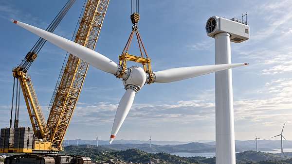
Wind rotor lifting equipment should be selected as part of a complete installation method statement, not as an isolated lifting accessory purchase or rental decision. The same turbine can require very different equipment depending on whether the project installs individual blades, lifts a pre-assembled rotor, uses a two-blade “bunny ear” configuration, or performs hub and blade work under restricted crane availability.
The central decision is whether the equipment can control the real load path and rotor geometry throughout the lift: from ground handling, through crane hook-up, to alignment at the nacelle. Rated capacity alone does not answer that question. A lifting frame with ample nominal capacity may still be unsuitable if it introduces unfavorable sling angles, excessive blade bending, insufficient clearance around the hub, or poor control during final bolt-hole alignment.
For project execution, the practical objective is to reduce the number of uncontrolled transitions. These include changing rigging at height, manually correcting blade pitch, transferring load between tools, or working close to a suspended rotor while wind conditions are changing. The best wind rotor lifting equipment is therefore the solution that fits the turbine manufacturer’s approved procedure, the crane configuration, the site envelope, and the expected weather window with the fewest avoidable interventions.
Define the Actual Lift Configuration Before Comparing Equipment
“Rotor lifting” covers several distinct operations. Treating them as equivalent is a common source of planning gaps.
- Single-blade installation uses a blade yoke, clamp, or dedicated blade lifting device, often combined with a tag-line arrangement and a separate root-end handling tool. It limits the suspended assembly weight but increases the number of lifts and nacelle-level connection activities.
- Pre-assembled rotor installation lifts the hub with all blades attached. This reduces work at hub height but creates a long, asymmetric, wind-sensitive load requiring a large working radius and carefully engineered lifting geometry.
- Two-blade rotor installation can reduce the gross suspended load compared with a full rotor lift while retaining some assembly benefits. It also creates a non-symmetrical configuration that may demand dedicated lifting beams, strict pitch positions, and defined blade orientation.
- Hub-only installation followed by blade installation changes the sequence of critical lifts. Hub lifting equipment must provide adequate access for connection, while blade tools must match the installed hub’s pitch and working positions.
The turbine OEM’s installation manual and approved lifting drawings must establish the baseline. They identify approved pick points, blade pitch angles, allowable handling loads, required fixtures, center-of-gravity assumptions, and restrictions on lifting in particular rotor positions. Generic tools should not be assumed compatible merely because their dimensions appear similar. Blade root interfaces, hub lifting lugs, pitch bearing arrangements, and allowable local shell loads vary by turbine platform.
Before requesting quotations or reserving equipment, freeze the intended installation sequence and identify every lift state. This includes transport support removal, ground assembly, rotor turn-over where applicable, main hoist connection, upending, nacelle approach, bolt engagement, and de-rigging. A tool that works during the main vertical lift but cannot be released safely after connection has not solved the full operation.
Rated Capacity Must Be Calculated at the Working Geometry
Selection should start with the maximum lifted mass, but that mass must be complete. Include the hub, blades, spinner components if lifted together, lifting beam, slings, shackles, spreaders, adapters, temporary fixtures, and any equipment suspended below the crane hook. The crane’s load chart must then be checked at the actual working radius, boom length, hook height, reeving arrangement, and configuration—not at its headline tonnage.
For the lifting equipment itself, capacity verification requires more than comparing the safe working load marked on a beam or yoke with the total assembly weight. The equipment must be assessed under its intended sling angles and load distribution. Sling tension rises sharply as sling angles flatten. A symmetrical two-leg arrangement may be easy to calculate, but rotor work is frequently not symmetrical: the hub center of gravity may be offset, blade pitch settings may alter geometry, and rigging legs may operate at different lengths or angles.
A qualified lift engineer should establish the load in each connection point for all relevant positions, including any upending phase. The governing condition is not always the final suspended orientation. During a transition from horizontal ground assembly to vertical lift, the center of gravity can move relative to the lifting points, placing temporary high loads into one sling, link, shackle, or attachment.
Capacity checks should also distinguish between static weight and dynamic effects. Crane acceleration, deceleration, slewing, hook block movement, wind-induced oscillation, and inadvertent contact can increase loads beyond the static calculation. The applicable project rules, equipment documentation, and lift classification should determine the required allowances and verification method. Capacity margins should never be used as a substitute for controlling wind and movement.
Center of Gravity and Blade Pitch Control Determine Whether the Rotor Is Manageable
A wind rotor is not a compact, naturally stable load. Its center of gravity can be displaced from the hook line, and its aerodynamic surfaces create large moments even in modest wind. Selection must therefore address both load support and attitude control.
For a complete rotor, the lifting arrangement must hold the hub and blades in the precise orientation required for nacelle connection. This can involve a hub lifting beam, blade support fixtures, rotor turning devices, and controlled tag-line systems. The equipment should be evaluated for its ability to maintain the required blade pitch positions without imposing unintended torsion or local compression on the blade shell.
For individual blades, the distinction between root-end support and outboard support is critical. The blade is a long composite structure with handling limits that differ from its in-service aerodynamic loading. A blade lifting yoke or clamp should support the approved section of the blade, distribute contact pressure as intended by the manufacturer, and prevent slippage or rotation. The tool’s interface materials, clamping mechanism, contact surfaces, and adjustment range all matter because surface damage, local crushing, or contamination can create quality issues that are not immediately visible.
Remote-controlled pitch or rotation capability can improve alignment and reduce personnel exposure, but it must be considered as part of a system. The project team needs to know who controls the device, how communication is maintained, what happens if power or signal is lost, how emergency release is prevented, and whether the tool can be manually secured in a safe position. Added actuation also adds inspection, maintenance, battery or hydraulic supply, and commissioning requirements.
Crane and Tool Selection Are Interdependent
The main crane cannot be selected independently from the rotor lifting arrangement. A long lifting beam, a below-hook rotor fixture, or a blade handling frame consumes hook height and can increase the required boom length. It may also move the center of the suspended load farther from the boom, increasing operating radius. These effects can shift the planned lift into a less favorable portion of the crane chart.
Hook height should be calculated from the ground elevation to the hub centerline, then adjusted for every suspended component: hook block, master links, slings, lifting beams, shackles, hub fixture, and required clearance for approach and alignment. Ground slope, crane settlement assumptions, nacelle elevation, and final connection position must be reflected in the calculation. A configuration that nominally reaches the hub centerline may leave insufficient travel for controlled lowering or rigging release.
Where a tailing crane is needed for rotor upending or ground handling, its role must be engineered with the same discipline as the main crane. The transfer of load from tailing crane to main crane is a defined critical phase. Equipment selection should confirm compatible connection points, sufficient separation between crane lines, no interference between booms or rigging, and a clear sequence for when the tailing connection is released.
For projects using multiple turbine models or different rotor diameters, verify interchangeability rather than assuming a tool is “adjustable.” Adjustment range does not prove structural approval for every configuration. The supplier’s documentation should explicitly cover the intended blade profile, root diameter, hub interface, lifting-point spacing, and maximum permitted mass.
Wind Limits Are an Equipment Compatibility Issue, Not Only a Site Rule
Rotor lifts are strongly affected by wind because blade area creates aerodynamic force and because the load is suspended at significant height. The relevant limit is not simply the wind speed measured at ground level. The lift plan should define the measurement location, instrument type, averaging method, gust treatment, communication protocol, and authority to stop the operation. Conditions aloft can differ materially from conditions at the crane base.
Equipment must be suitable for the wind limits adopted in the approved procedure. Long tag lines may provide some directional control but can expose personnel to line-handling hazards and are not a reliable method for overcoming excessive wind load. A rotor control device that is effective during calm conditions may not provide adequate authority when blade surfaces begin to generate substantial side force.
Planning should also consider the time needed to complete each irreversible stage. A forecast may support starting a lift, yet the available low-wind window may not be long enough for assembly checks, hook-up, upending, travel to elevation, alignment, bolting, and safe de-rigging. Equipment that simplifies final alignment can therefore have schedule value even where its rental cost is higher, because it reduces time spent with a rotor suspended near the nacelle.
Site Constraints Often Eliminate Otherwise Suitable Tools
Access roads, laydown arrangement, crane pad geometry, turbine spacing, overhead obstructions, and ground bearing conditions can determine the viable lifting method. A pre-assembled rotor may require a broad, level assembly area and enough clearance to rotate or upend the assembly. Single-blade installation may reduce ground-space demand but require more frequent delivery positioning and repeated high-altitude work.
Transport and mobilization constraints deserve equal attention. Large rotor beams and blade yokes can require special transport arrangements, lifting support during unloading, protected storage, and inspection after transit. Equipment availability should be evaluated by confirmed mobilization dates, not by a supplier’s general fleet listing. Delays in specialized rigging can stop turbine erection even if the main crane is already on site.
Offshore or near-shore work introduces further constraints, including vessel motion, marine corrosion exposure, deck securing, transfer limitations, and more restrictive weather criteria. Land-based tools should not be presumed suitable for marine operations without documented approval for that environment and lift method.
Documentation and Inspection Should Be Treated as Schedule-Critical Deliverables
A technically appropriate tool can still be rejected at site if its records are incomplete. Required documentation varies by jurisdiction and contract, but the project file commonly needs current inspection evidence, traceable identification, rated capacity markings, manufacturer instructions, lifting drawings, certificates for shackles and slings, maintenance records, and evidence that modifications have been approved.
In many jurisdictions, below-the-hook lifting devices are governed through national rules or recognized standards. Examples include EN 13155 for non-fixed load lifting attachments in Europe and ASME B30.20 and ASME BTH-1 in North American practice. These references do not replace the governing local regulation, client specification, crane supplier requirements, or turbine OEM procedure. Their practical importance is that they reinforce the need for identifiable design basis, inspection, marking, and controlled use.
Inspection should focus on the condition of the actual load-bearing and contact components: pins, bushings, welds, pad eyes, hydraulic hoses, clamps, locking mechanisms, load indicators, electrical controls, protective pads, and anti-slip surfaces. For blade contact tools, cleanliness and condition of pads are quality-control items as well as lifting items. Damage to a pad or incorrect placement may affect both grip and blade surface integrity.
Evaluate Equipment Suppliers by Engineering Support and Interface Control
For complex rotor work, the relevant supplier capability is not limited to supplying hardware. The project needs clear responsibility for engineering calculations, turbine-specific adapters, assembly instructions, inspection intervals, operator familiarization, spare parts, fault response, and technical support during commissioning.
A robust technical review should resolve several questions before the tool reaches site:
- Is the equipment explicitly approved or accepted for the intended turbine platform and installation arrangement?
- What is the verified total suspended weight, including all rigging and temporary equipment?
- Which lift positions create the highest connection loads and the least favorable center-of-gravity condition?
- What crane capacity and hook-height effects result from the complete below-hook assembly?
- How is blade rotation, pitch, or rotor orientation controlled during approach and connection?
- What wind limit applies to this particular configuration, and how is it monitored?
- Can the equipment be released and recovered without uncontrolled work at height?
- What inspections, certificates, and acceptance checks must be complete before the first lift?
Answers should be incorporated into the lift plan, not retained as separate supplier correspondence. If the equipment assumptions, crane study, and installation sequence are developed by different parties, interface inconsistencies can remain hidden until the work front is under pressure.
A Safer Choice Usually Reduces Complexity at the Critical Moment
Wind rotor lifting equipment is correctly selected when the approved tool, rigging geometry, crane configuration, site layout, and weather controls work as one installation system. The decision should be tested against the most demanding moment of the operation: often the upending transition, the final nacelle approach, or the release of lifting equipment after bolt engagement—not the uncomplicated vertical lift shown in a preliminary drawing.
Lower equipment cost is not a meaningful saving if it creates additional rigging changes, tighter wind sensitivity, insufficient alignment control, or uncertain certification. Conversely, a more specialized lifting solution needs justification through a clear reduction in exposure, execution time, or interface risk. The governing question is not which tool can lift the rotor, but which complete arrangement can install it within defined load limits, wind limits, access constraints, and quality requirements without creating uncontrolled work around a high-value suspended assembly.
Related News
 Sep 26, 2026How to Select Wind Rotor Lifting Equipment for Safe Blade and Hub InstallationWind rotor lifting equipment selection guide: ensure safe blade and hub installation with the right lift method, load control, crane compatibility, wind limits, and compliance.
 Sep 25, 2026What Drives Heavy Haulage Cost on Oversized Construction Equipment Moves?Heavy haulage cost explained: discover how load dimensions, route surveys, permits, escorts, lifting plans, and scheduling shape reliable oversized equipment transport budgets.
 Sep 24, 2026Supplier Management Frameworks That Reduce Delays on Large Construction ProjectsLarge-scale construction projects supplier management frameworks help prevent costly delays with risk-based controls, milestone tracking, quality oversight, and escalation plans for critical packages.
 Sep 23, 2026How to Evaluate a Paving Equipment Manufacturer for Highway ProjectsPaving equipment manufacturer evaluation guide for highway projects: compare reliability, paving quality, service support, compliance, and total cost of ownership.



Structural Load Expert
Weekly Insights
Stay ahead with our curated technology reports delivered every Monday.