
When Should Projects Specify Luffing-Jib Crawler Cranes for Restricted Sites?

When Should Projects Specify Luffing-Jib Crawler Cranes for Restricted Sites?
Restricted sites rarely fail because a lift is simply “too heavy.” More often, the problem is geometric: a module must pass above an operating pipe rack, a precast element must be placed behind a completed structure, or a vessel must be landed at elevation while a nearby building limits boom movement. In these situations, the choice of crane configuration can determine whether the lifting sequence remains practical, safe, and commercially defensible.
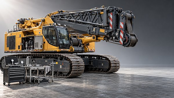
Crawler cranes with luffing jib configurations are often considered when a conventional main-boom arrangement cannot achieve the required combination of hook height, working radius, clearance, and placement control. They are not automatically the right answer for every congested project. A luffing jib adds capability, but it also introduces additional rigging, chart restrictions, assembly time, transport complexity, and operating constraints. The decision should be based on the actual lift envelope rather than the crane’s nominal maximum capacity.
For project managers, the central question is straightforward: does the site require the crane to reach a load position that a main boom, fixed jib, mobile crane, or alternative erection sequence cannot serve with adequate clearance and usable capacity? If the answer is yes, a luffing-jib crawler crane may be the most reliable solution.
What a Luffing Jib Changes in the Lift Envelope
A luffing jib is an articulated boom extension that can change its operating angle relative to the main boom. Unlike a fixed fly jib, it gives the crane team more flexibility to alter hook position and clearance while maintaining the basic crane location. In practical terms, it can help a crane work above an obstruction, extend the attainable hook height, or approach a placement point from a more favorable geometry.
That flexibility is particularly valuable where the load path is not a simple vertical hoist. A lift may need to clear structural steel, avoid a live process area, pass over a roofline, or set a component inside a partially enclosed industrial structure. Raising or lowering the jib can change the relationship between the hook, the boom head, the obstruction, and the final landing point. It can also permit certain lifts to be completed from a single crane position rather than requiring relocation or a more disruptive site rearrangement.
However, “more reach” should not be confused with “more capacity.” Capacity depends on the manufacturer’s chart for the exact configuration: crawler width, counterweight, main boom length, jib length, jib angle, reeving, operating radius, wind condition, and any approved special arrangements. The usable capacity at the required radius may be substantially different from a crane’s headline tonnage. The lifted load must also include hook block, slings, spreader beams, lifting beams, shackles, and any other below-the-hook equipment.
The Site Conditions That Usually Justify the Configuration
A luffing-jib configuration becomes worth serious consideration when constraints are persistent rather than occasional. If one isolated lift has a difficult clearance issue, an alternative crane position, temporary opening, or engineered lifting frame may be more economical. When multiple critical lifts share the same restricted geometry, the configuration can reduce repeated workarounds and stabilize the overall schedule.
Overhead obstructions control the load path
Pipe bridges, transmission lines, existing cranes, refinery structures, conveyors, bridges, roof trusses, and incomplete steelwork can limit the route between the pick point and the set point. The question is not merely whether the load clears the obstacle at rest. The lift team must assess the full travel path, including boom and jib deflection, load swing allowance, rigging height, hook approach, and the possibility of a changed radius during slewing or hoisting.
A luffing jib can create a higher or differently shaped working envelope, allowing the hook to approach from above where a main boom alone would conflict with the obstruction. This is commonly relevant in brownfield industrial work, power-plant upgrades, petrochemical maintenance, and dense urban construction where the crane cannot simply be repositioned on open ground.
The crane must work close to existing structures
Restricted sites often have limited laydown space and few viable crane pads. A crawler crane may need to operate from one engineered location while serving several erection zones. If adjacent buildings, excavation edges, operating units, or public boundaries prevent the crane from moving closer, a luffing jib may provide the height and radius needed to make the fixed crane position viable.
This does not eliminate footprint concerns. The project still needs to account for crawler track loading, crane travel routes, counterweight clearance, tail-swing zones, assembly space, and access for delivery trailers. A crane that clears the load-side obstacle but cannot safely swing its rear counterweight is not a workable solution.
High-elevation installation requires controlled placement
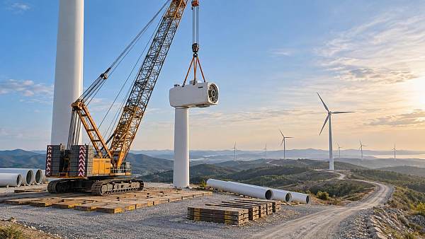
Structural modules, elevated process equipment, bridge components, wind-energy elements, and major mechanical assemblies can demand both elevation and placement accuracy. Where the final connection point sits behind or above an obstruction, a luffing jib may preserve a more controlled hook approach than an excessively long main boom or a crane positioned at an unfavorable radius.
The benefit is not simply height. It is the ability to manage geometry during the lift. Project teams should verify whether jib luffing will be used only during setup or whether it forms part of the planned motion sequence. The latter requires particularly careful review of chart conditions, operational procedures, communication protocols, and clearance margins.
A Decision Test: Geometry Before Crane Tonnage
Many early crane selections begin with the component weight. That is necessary, but it is not enough. On constrained sites, begin with a scaled lift study or digital site model that shows the complete lifting envelope. The model should include the actual pick elevation, final set elevation, required radii, obstruction heights, crane centerline, allowable crane positions, and all permanent and temporary structures likely to be present when the lift occurs.
This approach often reveals whether the restricted site truly needs crawler cranes with luffing jib capability or simply needs better sequencing. For example, installing a steel frame before roof closure, moving a temporary facility, or reserving a wider access corridor can sometimes avoid a specialized configuration. Conversely, a lift study may show that those changes would disrupt more work than the crane solution costs.
Where the Trade-Offs Become Material
The luffing-jib option should be evaluated as a project system, not as a crane attachment. Additional lattice sections, pendants, inserts, transport loads, assembly activity, and potentially an assist crane can affect mobilization planning. The site team may require a larger exclusion zone during assembly and a more disciplined interface plan once the crane is operating near other trades.
Ground conditions deserve the same attention as boom geometry. Crawler cranes distribute loads through tracks, but that does not make weak or variable ground acceptable. The bearing pressure and load distribution must be assessed for the exact crane configuration and operating condition, including travel if travel under load is contemplated. Crane mats, temporary works, buried services, excavation influence zones, and differential settlement risks should be reviewed by the appropriate competent parties.
Wind is another frequent source of mistaken confidence. A luffing jib can increase the exposed area and sensitivity of the system, particularly where long, slender components or large surface-area loads are being handled. The applicable manufacturer guidance, site wind-monitoring procedures, load characteristics, and local lifting requirements need to be incorporated into the lift plan. A generic site wind limit is not a substitute for configuration-specific review.
Do Not Treat Clearance as a Static Measurement
One of the most expensive planning errors is checking only the crane’s nominal dimensions against the obstacle. Real lifts are dynamic. The boom can deflect under load, the jib angle can change, the load can rotate, and rigging can shift as the component moves from the pick position to the installation point. Even a carefully prepared model should be tested against field conditions, actual elevations, crane setup tolerances, and the latest construction status.
The same principle applies to overhead utility lines and operating plant. These interfaces may demand controlled zones, isolation measures, approved procedures, or coordination with asset owners under local rules. They should be resolved early, not treated as a final lifting-day issue. If required clearances cannot be reliably maintained, changing the crane type alone will not remove the underlying risk.
Alternatives Worth Testing Before Committing
A luffing-jib crawler crane is strongest when its flexibility addresses a real constraint across a meaningful sequence of work. Before committing, test several alternatives against the same lift envelope: a different crawler-crane position; a main-boom-only configuration; a fixed-jib arrangement; a higher-capacity crane at a shorter radius; a mobile crane where access and outrigger support permit; or a revised installation sequence.
The comparison should not stop at day rate or mobilization cost. Consider the number of crane moves, temporary works, disruption to adjacent operations, required closures, erection duration, risk of weather-sensitive critical lifts, and consequences of delayed access. A technically elegant crane plan may be commercially weak if it requires too much site preparation. Equally, a seemingly costly luffing-jib arrangement can be justified when it avoids repeated shutdowns or enables installation before a critical construction milestone.
Building a Defensible Specification
A useful specification should describe the work required, not prematurely lock the project into a particular model. Define the maximum gross load, pick and set elevations, working radii, physical restrictions, site access limits, anticipated crane positions, ground-information status, required operating dates, and whether the crane must travel, slew, or luff while loaded. State the critical obstruction clearances and identify interfaces with other contractors or operating assets.
Then require the lifting contractor or crane provider to submit the proposed configuration, relevant load-chart basis, crane layout, assembly plan, ground-support assumptions, transport requirements, and lift methodology for review. The project should confirm that the submitted arrangement reflects the actual site sequence rather than an early drawing that no longer matches field conditions.
This is where intelligence-led planning has practical value. TF-Strategy follows crawler cranes as part of the wider heavy-equipment system supporting wind, nuclear, petrochemical, tunnelling, mining, and major infrastructure work. Its Strategic Intelligence Center connects machinery parameters with construction methods and project constraints—the relationship that matters most when a crane selection is being made under pressure. For restricted sites, the useful question is not which machine appears largest on paper, but which configuration creates a safe, repeatable, and supportable lifting path.
Specify a luffing-jib crawler crane when clearance geometry, fixed crane positions, elevated placement, and repeated constrained lifts make that flexibility necessary. Do not specify it simply because the site is crowded. A verified lift envelope, configuration-specific capacity review, realistic ground plan, and constructible assembly strategy will show whether the added complexity is a safeguard for delivery—or an expense the project can avoid.
Related News
 Oct 20, 2026Which Heavy Machinery Maintenance Standards Apply to Your Construction Fleet?Discover which heavy machinery maintenance standards apply to your fleet. Clarify legal duties, OEM requirements, and inspection rules to reduce risk and keep equipment ready for work.
 Oct 19, 2026Sizing Industrial Hydraulic Power Packs: Pressure, Flow, and Duty CycleSize industrial hydraulic power packs with confidence. Learn how pressure, flow, and duty cycle affect performance, energy costs, and heat control—and avoid costly sizing mistakes.
 Oct 18, 2026How Equipment Specifications Affect Purchase, Installation, and Operating CostsExplore equipment specification planning cost factors that shape purchase, installation, and operating budgets. Compare lifecycle costs, avoid oversizing, and buy with confidence.
 Oct 17, 2026Tunnel Boring Machine Supplier List: Compare TBM Types and Service CoverageExplore our tunnel boring machinery supplier list to compare EPB, slurry and hard rock TBMs, assess service coverage and lifecycle costs, and build a smarter procurement shortlist.

Structural Load Expert
Weekly Insights
Stay ahead with our curated technology reports delivered every Monday.