
What Lifting Capacity Is Required for Petrochemical Modules?
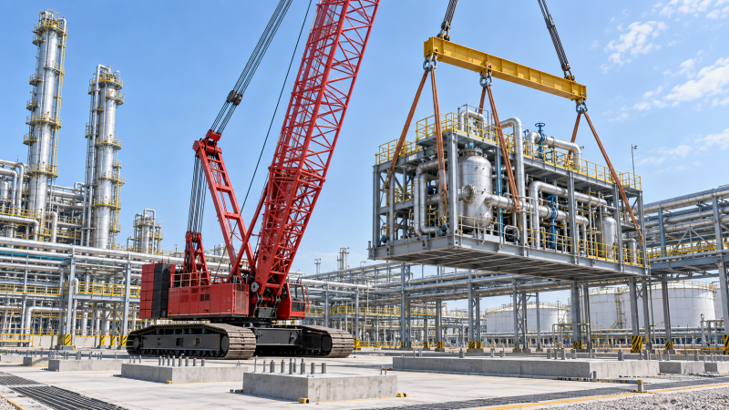
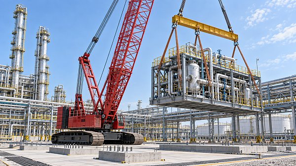
A petrochemical module does not require a crane with a capacity equal to its shipping weight. Required lifting capacity is determined by the total suspended load at the planned operating radius, then checked against the crane's rated load chart for its exact boom, jib, counterweight, track position, ground condition, and reeving configuration. A 400-tonne module lifted close to the crane can demand less capacity than a lighter module installed at a long radius. Conversely, a nominally large crawler crane can be unsuitable if its chart falls sharply at the required boom length and radius.
The starting point is the module's verified lift weight, but the planning calculation must include rigging, lifting beams, hook block, slings, shackles, spreader frames, temporary lifting lugs, and any attached installation hardware that remains on the module during the lift. The resulting gross load is then compared with the crane's allowable capacity at the actual pick and set positions, rather than with a headline crane class.
Start with the gross suspended load
Module weight should come from a controlled lifting data package, not from an early fabrication estimate. Petrochemical modules often incorporate pipe racks, vessels, exchangers, cable trays, insulation supports, access platforms, valves, instrument tubing, and loose completion items. These additions can change the final lifted mass and, just as importantly, shift the center of gravity.
A useful planning equation is:
Gross suspended load = module lift weight + rigging weight + hook block weight + lifting accessories carried by the crane
Rigging is frequently understated during preliminary crane selection. A module may require a multi-point lifting frame to distribute forces across designated trunnions or padeyes. Long slings, large shackles, equalizer beams, and a heavy spreader can add substantial load. The crane's hook block and overhaul ball are also chart deductions on many configurations. If the chart states a gross rated capacity, all suspended items must be accounted for; if it states a net capacity after certain deductions, the chart notes must be read carefully.
Temporary steel added for lifting also deserves attention. Reinforcement around lifting lugs may be part of the module's certified lift weight, while removable transport stools or temporary bracing may be removed before the final setting operation. Treating all temporary steel as either included or excluded without confirming the lift sequence produces inaccurate load cases.
Capacity is governed by radius, not by crane nameplate
Crawler crane capacity is highly sensitive to operating radius. Radius is the horizontal distance from the crane's center of rotation to the vertical load line, not the distance from the track edge, boom foot, or module transport route. It changes throughout the lift as the boom luffs, the crane swings, the load is upended, or the crane travels under load where that operation is permitted by the approved configuration.
The maximum radius is often at the final set position, not at the initial pick. A module lifted from a transport vehicle may initially be close to the crane, then be swung over pipe corridors, foundations, existing steel, or temporary works. The load line can move outward as clearance is created around an obstruction. A plan based only on the pick radius can select a crane that cannot safely perform the final placement.
For a given boom length, the load chart normally declines as radius increases. Longer boom may create needed reach but also reduces capacity. Adding a luffing jib or fixed jib can alter the chart further. The correct question is therefore not, "Is this a 1,000-tonne crane?" It is, "What is the allowable load for this machine in the exact configuration at the maximum verified radius?"
Center of gravity changes both the load path and the radius
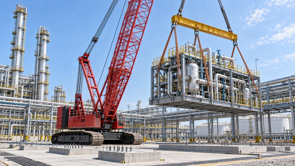
Petrochemical modules are rarely uniform boxes. A vessel bank on one side, an elevated pipe rack, a furnace-related structure, or densely routed large-bore piping can place the center of gravity far from the geometric center. The marked center of gravity must be based on the final lifted condition, including fluids, loose equipment, preservation materials, and items intentionally retained for installation.
An incorrect center of gravity causes more than an inconvenient tilt. It changes sling tensions, can overload one lifting point, moves the load line relative to the crane, and may prevent the module from passing safely through a restricted opening. A tilted module may also strike permanent steelwork even when its nominal envelope appeared clear in a drawing.
Four-point lifts require special care because equal loading across all legs does not occur automatically. Fabrication tolerances, lug elevations, sling lengths, structural deflection, and center-of-gravity offset can transfer a larger share of load to one point. Equalizer beams, engineered rigging geometry, and measured sling lengths are used to control this distribution. Crane capacity must be reviewed against the load actually carried by each crane in a multi-crane lift, including the transient loads created during synchronization or load transfer.
Read the load chart as a configuration document
A crane chart is not a general statement of capability. It is valid only under stated conditions. Before using a capacity figure, confirm the boom type and length, counterweight arrangement, carbody counterweight where applicable, track width or track position, lift mode, parts of line, hook block, wind limits, and whether the crane is stationary or moving. Chart notes may restrict side loading, require level ground, limit boom angle, or prohibit a configuration with certain attachments installed.
The number of parts of line does not increase structural crane capacity. Reeving must be sufficient for the line pull and hook block arrangement, but adding parts of line only permits the hoist system to handle the load within its wire-rope limits. A crane can have adequate line pull while remaining limited by boom strength, tipping stability, or a chart restriction at the relevant radius.
Capacity must also be checked against the relevant duty classification. A stationary main-boom lift, a lift with a luffing attachment, a pick-and-carry movement, and a tailing operation may each use different chart provisions. Do not apply a static rating to a dynamic travel case or assume that a crane can slew through the planned arc at the same capacity available over its most favorable sector.
Choose the crane from the controlling lift condition
For many module installations, the controlling condition is one of the following:
- Final set at maximum radius: the module clears a structure and is lowered onto supports while the boom is at its least favorable angle.
- Initial breakout: the module separates from a transporter or fabrication stool, revealing an unplanned load share, binding condition, or center-of-gravity shift.
- Rotation or tailing: one crane takes a changing share of the weight as a horizontal module is brought upright.
- Restricted boom geometry: a nearby rack, flare line, building, or energized system prevents the boom from using the otherwise preferred approach.
- Crane travel or repositioning: the route imposes reduced capacity, uneven ground exposure, or a radius increase at a turn.
Each condition should be calculated separately. Selecting capacity from a single maximum module weight overlooks the fact that the heaviest module is not always the most difficult lift. A lighter module with a high center of gravity, a long outreach, or narrow clearance can control crane selection.
Allowances should be explicit, not assumed
Heavy-lift planning includes engineering allowances, but they should not be treated as a universal percentage added casually to the module weight. The required margin is influenced by the approved lift basis, the precision of weight and center-of-gravity information, the nature of the lift, potential dynamic effects, and the crane manufacturer's chart conditions. The project lifting procedure should define the acceptance criteria.
Uncertainty should be reduced at the source whenever possible. Weighing a completed module, reviewing fabrication changes, confirming installed equipment, and verifying rigging weights are stronger controls than relying on a large unspecified contingency. A late-discovered weight increase can force a different boom configuration, a crane upgrade, a revised set location, or a complete rework of the lifting study.
Wind deserves its own assessment. Wind loading is driven by projected area, shape, elevation, and orientation, not merely by module mass. Pipe racks with open steel can behave differently from clad process modules or equipment skids with large vertical surfaces. A module may remain within crane load capacity while exceeding the allowable wind condition for controlled handling. Wind limits for the crane, rigging, and module all need to be compatible.
Ground support can limit a large crane before its chart does
A crawler crane's rated chart assumes the support conditions specified by the manufacturer. On a petrochemical site, the actual ground may include compacted fill, buried utilities, underground drainage, existing foundations, pipe trenches, temporary mats, or partially completed roads. Track bearing pressure changes with the crane's configuration and load direction, and local support conditions may vary along the swing path.
Crane mats do not automatically solve inadequate bearing capacity. Their dimensions, stiffness, joint arrangement, and contact with the prepared surface determine how load is distributed. Differential settlement can affect levelness and therefore boom geometry. A small change in crane inclination can reduce available margin and can alter the load path during a precision set.
The crane foundation review should cover the full operating area: assembly location, lifting position, swing sector, travel route, and any place where counterweight or crane components pass close to excavations or buried structures. Access for the module transporter and rigging crew also matters, because a workable crane pad is of limited value if the load cannot be presented at the planned pick point.
Module interface details determine whether the planned capacity is usable
Lifting lugs, trunnions, and padeyes must be designed for the actual rigging angles and load distribution, not simply for a vertical share of the module weight. Sling angle increases leg tension. Side loading, out-of-plane loading, and local shell or frame reinforcement need evaluation where relevant. A lift point rated for transport might not be suitable for an installation lift with a different orientation or spreader arrangement.
Headroom is another common constraint. Hook block depth, shackle body length, sling length, spreader depth, and the distance between lifting lugs all consume vertical clearance. An installation can have sufficient crane chart capacity yet fail because the module cannot be lifted high enough to clear supports or pass above adjacent steel. Shorter rigging may improve headroom, but it can increase sling angles and lug loads. The solution must satisfy both constraints together.
Clearance studies should use the full moving envelope: module, rigging, hook block, boom, tail crane if used, and transport equipment. Fixed interferences are only part of the issue. Flexible hoses, suspended lines, loose temporary works, and unremoved scaffold sections can create field conflicts that were absent from the model.
When one crane is insufficient or impractical
Tandem lifting may be considered when a module must be upended, when its geometry creates an unacceptable single-crane radius, or when a tail crane is needed to control rotation. This does not simply divide the module weight between two crane capacities. The load share changes as the geometry changes, and the most demanding instant may occur near breakout, during rotation, or when one crane releases the load.
A tandem plan requires defined crane positions, boom geometries, rigging lengths, communication method, release sequence, and a clear method for controlling unintended load transfer. The allowable capacity of each crane must be checked at every significant stage. If the lift requires travel, the limitations of both cranes and the effect of ground variation must be reviewed together.
Sometimes a larger single crawler crane is operationally simpler than a tandem lift, yet site congestion, assembly space, access routes, or ground preparation can make that option impractical. The viable capacity is therefore the capacity of a complete lifting system: crane configuration, rigging, engineered lift points, ground support, geometry, and available space.
Frequently Asked Questions
Can the module shipping weight be used for crane selection?
It is suitable only as an early screening input. Final selection requires the verified installation lift weight, all suspended rigging and hook components, the maximum operating radius, and the confirmed crane configuration.
Why can a smaller module require a larger crane?
Longer radius, greater hook height, an unfavorable center of gravity, restricted crane placement, or a complex lifting frame can make a lighter module more demanding than a heavier module installed close to the crane.
Does extra crane capacity remove the need for lift engineering?
No. Extra chart capacity does not resolve overloaded lifting lugs, insufficient headroom, inadequate ground bearing, an incorrect center of gravity, or conflicts along the lift path. These conditions must be resolved in the engineered lift arrangement.
The required lifting capacity is the approved chart capacity that remains adequate at every planned stage of the lift after gross load, radius, configuration, site support, module behavior, and procedural allowances have been established. That calculation produces a defensible crane choice; a nominal tonnage alone does not.
Related News
 Oct 06, 2026Selecting Petrochemical Overhead Cranes for Hazardous Areas and Heavy Process LoadsPetrochemical overhead cranes for hazardous areas: learn how to match capacity, duty, controls, corrosion protection, and maintenance access for safer, reliable lifts.
 Oct 05, 2026Tunneling Equipment Specification Planning: Key Criteria for Ground and Project RisksEquipment specification planning tunneling: learn how to match TBM systems to ground risks, geometry, safety, logistics, and lifecycle cost for more reliable project delivery.
 Oct 04, 2026Nuclear Lifting Equipment Cost: Budgeting for Compliance, Testing, and Lifecycle RiskNuclear lifting equipment cost explained: budget for compliance, proof-load testing, installation, documentation, and lifecycle risk to make confident procurement decisions.
 Oct 03, 2026How to Assess TBM Manufacturers for Hard-Rock Tunneling Projects?Choose the right tunnel boring machine manufacturer for hard-rock projects. Explore key criteria for design, lifecycle cost, factory quality, and service support.

Structural Load Expert
Weekly Insights
Stay ahead with our curated technology reports delivered every Monday.