
A Field Guide to Repairing Road Construction Equipment Before Downtime Escalates
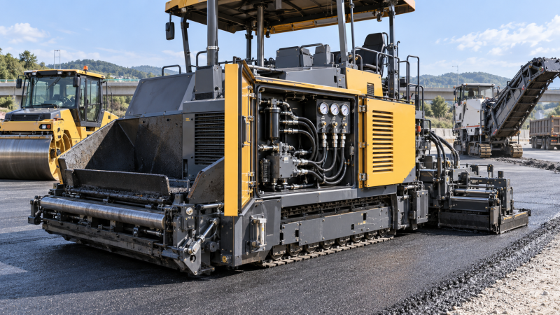
A paving train rarely stops because of one dramatic failure. More often, a roller begins to lose vibration on one drum, a paver screed heats unevenly, a milling machine starts leaving an inconsistent cut, or a hydraulic function becomes slow enough that the operator compensates with control inputs. By the time the machine is taken out of service, a repair that could have been planned between shifts may have become a delay involving parts, cleanup, transport, and schedule pressure.
The practical rule for repairing road construction equipment before downtime escalates is to diagnose the failure pattern before replacing components. Start with the machine’s operating condition, safety status, fault history, fluid condition, and visible mechanical evidence. Then isolate the affected system—hydraulic, electrical, drivetrain, heating, vibration, conveyor, or control—and confirm the cause with measurements rather than assumptions. This approach avoids the costly habit of replacing a failed symptom while leaving the underlying restriction, poor connection, contamination source, or mechanical misalignment in place.
When a minor complaint deserves immediate attention
Not every warning light requires a full shutdown, but certain changes should move to the top of the service queue. A road machine works under heat, dust, vibration, shock loading, and repeated direction changes. Those conditions can turn small defects into compound failures quickly, particularly when a failing component affects a shared hydraulic circuit, engine cooling system, charging system, or traction drive.
Escalate the inspection when the complaint involves any of the following:
- Repeated hydraulic temperature alerts, slow cylinder movement, erratic travel response, or visible oil aeration.
- Loss of braking performance, unusual steering effort, unstable travel speed, or one-sided drive behavior.
- Electrical alarms that return after reset, intermittent display loss, blown fuses, charging faults, or harness damage near moving joints.
- Abnormal bearing noise, vibration that changes with speed, recurring loose fasteners, or metal particles found during lubrication checks.
- Uneven mat texture, unstable screed temperature, poor material flow, inconsistent milling depth, or roller vibration that cuts in and out.
- Coolant loss, elevated engine temperature, belt debris, fuel dilution concerns, or exhaust-related derate messages.
A single event may be caused by a sensor or operator setting. A repeated event under the same load, temperature, or machine position is different: it is diagnostic information. Record when it occurs, which functions are active, whether the machine is hot or cold, and whether the symptom changes with engine speed. Those observations are often more useful than a generic description such as “hydraulics are weak.”
Start with a controlled inspection, not a parts order
Before disconnecting hoses or opening electrical enclosures, make the machine safe for inspection. Park on stable ground, lower supported implements, secure articulated sections where applicable, apply the parking brake, isolate energy sources, and follow the manufacturer’s lockout procedure. Hydraulic accumulators, hot asphalt-contact surfaces, rotating drums, conveyors, and elevated screeds can retain hazardous energy after the engine is stopped.
Next, establish the machine’s current condition. Review active and stored diagnostic codes, but do not let a code become the diagnosis. A low-pressure code can result from a worn pump, suction restriction, internal leakage, a relief-valve problem, oil viscosity outside the operating range, a damaged sensor circuit, or a command issue. Use the code to identify the circuit and conditions to test.
- Confirm the complaint. Run the function only when it is safe to do so. Note the response time, noise, pressure behavior, temperature, and any changes as load increases.
- Look for external evidence. Check hose routing, fittings, cylinder rods, wiring clamps, connectors, belt condition, fastener witness marks, and debris around moving assemblies.
- Check basic service conditions. Verify fluid levels, filter restriction indicators, battery terminals, ground straps, air intake condition, coolant level, and grease delivery.
- Measure against the correct specification. Use approved pressure ports, electrical test points, temperature measurements, and calibration procedures. A reading without the correct test condition can mislead the repair.
- Inspect the cause of the defect. When a failed hose, fuse, bearing, or sensor is found, determine why it failed before installing a replacement.
Service history matters at this stage. Repeated filter changes, recurring connector corrosion, frequent track-adjustment issues, or multiple repairs in the same hydraulic area may show a pattern that is invisible during a single repair event.
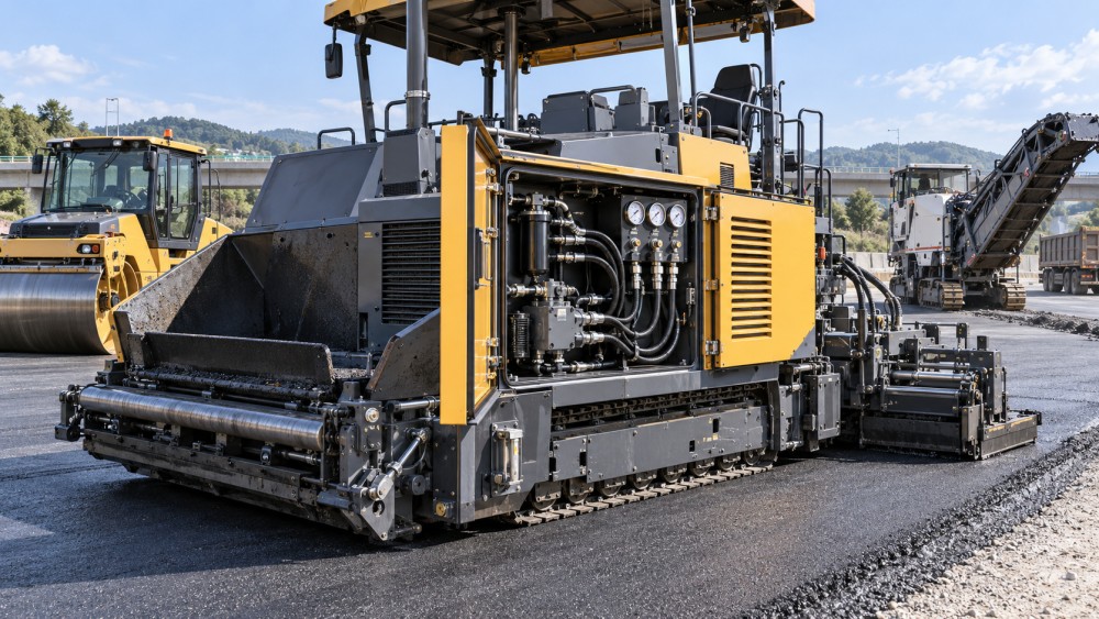
Hydraulic faults: separate pressure loss from flow loss
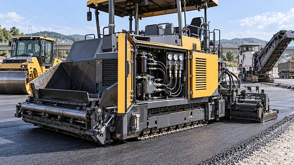
Hydraulic systems create some of the most disruptive failures in pavers, rollers, reclaimers, cold milling machines, and material transfer equipment. Yet “low hydraulics” is not a useful diagnosis. Pressure indicates resistance to flow; flow determines actuator speed. A system can reach pressure but move slowly because of low pump delivery, excessive internal leakage, a restricted filter, a partially collapsed suction hose, or a valve that does not fully stroke.
Symptoms that point toward contamination or restriction
Foamy oil, a whining pump, intermittent function after a filter change, or a hydraulic tank level that rises abnormally can indicate air entry, return restriction, or fluid-management trouble. Inspect suction-side clamps and hoses closely; small leaks on the suction side may draw air without leaving an oil drip. Check whether the oil grade matches ambient conditions and the machine specification. Fluid that is too cold, too hot, or contaminated with water can alter response and accelerate wear.
When a filter element is removed, do not discard the evidence immediately. Visible metallic debris, dark friction material, or unusual particulate matter can change the repair scope. A component replacement without circuit flushing, reservoir inspection, and contamination control can expose the new part to the same damaging material.
Pressure tests need a load and a comparison point
Use calibrated gauges or approved electronic test equipment at the designated ports. Compare standby pressure, relief pressure, charge pressure, and case-drain flow only under the conditions specified for that machine. A travel drive may appear normal without load but fail when climbing, cutting, compacting, or feeding material. Conversely, forcing a system to relief pressure for extended periods can create heat and damage components.
Case-drain testing is especially useful when a hydrostatic drive or hydraulic motor loses performance without obvious external leakage. Excessive case flow may indicate internal wear, but the interpretation depends on oil temperature, commanded displacement, speed, and the service specification. Do not condemn a pump or motor based only on noise or a single pressure reading.
Electrical problems often begin where the harness moves
Road equipment wiring is exposed to vibration, water spray, heat, abrasion, and repeated articulation. Electrical faults may disappear when the machine is parked in the workshop, then return when the screed extends, the drum vibrates, or the conveyor moves. Begin with the fault code and circuit diagram, then inspect the sections of harness that bend, rub, pass through brackets, or sit near exhaust components and hydraulic lines.
A visual check is necessary but incomplete. A connector can look clean while having poor terminal tension, internal corrosion, or a broken conductor beneath intact insulation. Check supply voltage, ground integrity, voltage drop under load, and continuity with the circuit isolated as required. A static continuity test may not reveal a wire that opens only under vibration. Gentle harness movement during an approved diagnostic test can help locate intermittent faults without damaging the insulation.
When repairing a harness, use methods suited to vibration and environmental exposure. Unsupported splices, incorrect crimping, and poorly sealed repairs often create a second failure point. Restore loom protection, clamp spacing, bend radius, and routing so the repair does not rub against moving or hot components.
Repairing paver and compaction issues without masking the cause
Paving quality complaints can originate from the machine, the material supply, operating technique, grade-control settings, or conditions at the work surface. The maintenance task is to distinguish a machine defect from a process variation before adjusting components blindly.
For a paver that produces uneven temperature or inconsistent material distribution, inspect screed heater circuits, connections, sensor feedback, generator output, and control commands. Also examine conveyors, augers, chain tension, drive motors, feeder sensors, and accumulated material around moving parts. A material-flow issue may feel like a screed problem because the final symptom is visible at the mat.
With rollers, intermittent vibration may result from an electrical interlock, low charge pressure, hydraulic motor wear, a control-valve issue, or a mechanical defect in the eccentric system. Listen for changes between high and low amplitude modes, inspect mounting hardware and isolators, and verify that the fault is not linked to travel speed or an operating inhibit. Continued operation with abnormal drum vibration can damage bearings, housings, and mounts beyond the original repair.
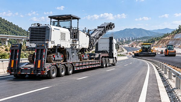
On milling equipment, an uneven cut may require inspection of grade-control inputs, ski or sensor condition, cutter drum wear, tool holder damage, rotor balance, track response, and hydraulic drive performance. Replacing worn picks alone will not correct a control problem; recalibrating a sensor will not solve a damaged drum or inconsistent track movement.
Use the repair to prevent the next shutdown
A completed repair is not only the moment when the fault code clears or the machine moves again. Confirm the restoration under the operating conditions that produced the complaint. Run the affected function through its normal range, check for leaks after warm-up, verify protective covers and clamps, clear codes only after recording them, and confirm that no related alarms return.
Document the original symptom, the confirmed cause, measurements taken, parts replaced, contamination found, adjustments made, and post-repair result. Clear notes reduce repeat diagnostic time when the same machine returns with a related issue. They also reveal whether a recurring defect is tied to a particular operating condition, maintenance interval, cable route, hose assembly, or subsystem.
Some repairs should trigger a broader inspection before release. A burst hydraulic hose warrants checking nearby hoses for abrasion and clamp failure. A burned electrical connector calls for examination of terminal fit, circuit load, moisture entry, and upstream protection. A failed bearing should lead to checks of lubrication, alignment, sealing, preload, and the condition of mating components. Treating these as isolated parts failures is how small defects become unplanned downtime.
Know when the machine should stay out of service
Take the equipment out of operation when there is a risk of uncontrolled movement, brake degradation, hydraulic injection hazard, fuel leakage, overheating, exposed rotating components, structural cracking, damaged lifting points, repeated electrical resets, or a condition that prevents the machine from maintaining predictable travel, steering, cutting, paving, or compaction performance. Temporary bypasses may restore a function, but they can also defeat protections and make later diagnosis harder.
For complex hydrostatic, electronic-control, or screed-calibration faults, use the manufacturer’s current service procedures and approved diagnostic tools. The goal is not merely to get the machine through the next shift. It is to return it with the fault mechanism understood, the repair verified, and the conditions that caused the problem addressed before they create a larger interruption.
Related News
 Oct 17, 2026Tunnel Boring Machine Supplier List: Compare TBM Types and Service CoverageExplore our tunnel boring machinery supplier list to compare EPB, slurry and hard rock TBMs, assess service coverage and lifecycle costs, and build a smarter procurement shortlist.
 Oct 16, 2026Heavy-Duty Petrochemical Lifting: Selecting Cranes by Load, Radius, and Site AccessExplore heavy-duty petrochemical lifting solutions. Compare cranes by load, radius, site access, and ground support to reduce project risk and optimize lifting costs.
 Oct 15, 2026Crane Selection for Petrochemical Turnarounds: Capacity, Radius, and Site AccessExplore petrochemical lifting solutions cranes can deliver, with expert guidance on capacity, working radius, and site access to help you plan a safer, more efficient turnaround.
 Oct 14, 2026High-Capacity Heavy Lifting Solutions: Matching Load, Radius, and Ground ConditionsDiscover heavy lifting solutions high capacity projects demand—compare load charts, working radius, and ground conditions to select a feasible, cost-effective system.
Pavement Process Engineer
Weekly Insights
Stay ahead with our curated technology reports delivered every Monday.