
Preventing Pipeline Blockages in Cutter Suction Dredging Projects
Preventing Pipeline Blockages in Cutter Suction Dredging Projects
A blocked discharge pipeline can turn an otherwise productive cutter suction dredging operation into a costly recovery exercise. Production falls immediately, the pump may run outside its intended operating range, and the crew may have to stop excavation before the location of the restriction is even known. In severe cases, repeated pressure surges can damage pipe joints, hoses, valves, liners, or pump components.
Most blockages do not begin as a single dramatic event. They usually develop through a chain of smaller deviations: the material becomes coarser than expected, the cutter head releases a compacted lump, water supply to the suction side changes, a pipeline section settles, or the operator keeps increasing production despite a rising discharge pressure. Preventing these events depends on matching dredger capability, pipeline layout, material conditions, and operating discipline.
For operators, the practical objective is not simply to move the highest possible volume of slurry. It is to maintain a stable slurry flow in which solids remain suspended and the pipeline can transport the mixture without excessive pressure, wear, or interruption.
How a Pipeline Blockage Develops
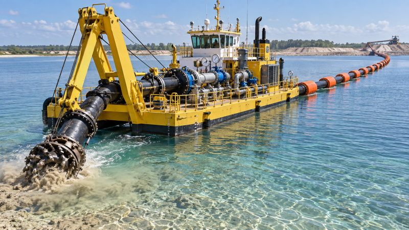
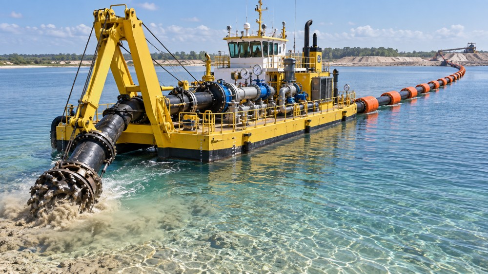
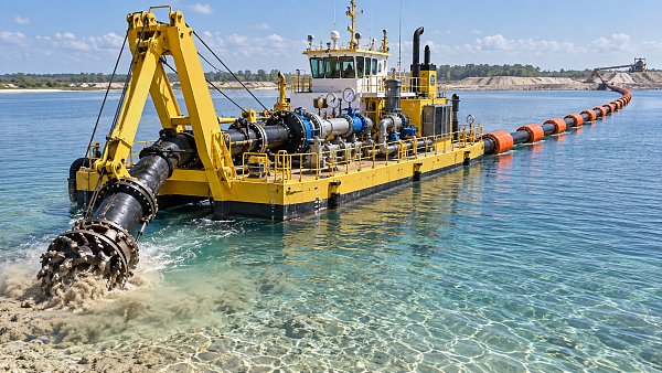
A cutter suction dredger creates a slurry by loosening soil with the cutter head, mixing it with water, and drawing the material through the suction line to the dredge pump. The pump then sends that mixture through a floating, shore, or submerged discharge pipeline. The transport system works only while the flow velocity is high enough to keep the expected particles moving.
When velocity drops below the level needed for the actual material in the line, heavier particles can begin to settle. A thin bed of sand, gravel, shell fragments, clay lumps, or debris may form at a low point in the pipeline. Once the effective pipe diameter becomes smaller, resistance increases. Pressure rises upstream, velocity can fall further, and the deposit may grow quickly into a full obstruction.
Blockages also occur when oversized material enters the system. A cutter head may break loose consolidated clay, rock fragments, timber, scrap metal, roots, or geotextile remnants that are not compatible with the suction opening, pump passage, or discharge pipe diameter. In this situation, increasing pump speed alone may not solve the problem and can expose the system to unnecessary stress.
Operators should treat discharge pressure, vacuum, engine load, flow behavior, and visible pipeline movement as related signals. A pressure increase without a corresponding improvement in production is often more meaningful than any single instrument reading.
Recognizing Early Warning Signs Before the Line Stops
A complete blockage is easier to identify than an emerging one. By that stage, the crew may be dealing with a settled pipeline, trapped material, and a long shutdown. The better approach is to respond when the operating pattern starts to drift.
- Rising discharge pressure: A gradual increase can indicate growing friction losses, a developing deposit, a partially closed valve, pipe wear changes, or a restriction downstream.
- Unstable suction vacuum: Sudden fluctuations may point to irregular cutter feeding, air entering the suction system, cavitation, or intermittent passage of large material.
- Reduced production at similar engine load: If the dredger is using similar power but moving less material, the pipeline and pump operating condition should be checked before forcing higher output.
- Abnormal floating pipeline behavior: A pipeline that sits unusually low, shifts sharply, or shows inconsistent slurry movement may have a localized accumulation or a damaged connection.
- Repeated pump clogging: Frequent pump or suction blockage can signal that the material is too coarse, too fibrous, too adhesive, or too contaminated for the current arrangement.
These signs need to be interpreted against the job conditions. A pressure change after adding pipe length is not automatically a blockage warning. Nor is a lower density always a problem if the excavation face has changed. The key is to compare current readings with the normal operating pattern for the same pipeline route, cutter depth, and material type.
Start With the Material, Not the Pump
Pipeline problems are often described as pump problems because the pump is where pressure becomes visible. Yet the root cause frequently begins at the excavation face. Before starting a new reach, operators should assess whether the deposit is mainly loose sand, fine silt, cohesive clay, gravel-bearing soil, weathered rock, mixed fill, or dredged material containing debris.
Fine sand and silt can usually be transported at lower velocity than coarse gravel or mixed material, but highly fluid fine material can create another risk: poor solids concentration. Too much water may keep the line clear while producing an uneconomical amount of transported water. Cohesive clay may travel as large sticky lumps instead of a uniform slurry. Those lumps can lodge at elbows, reducers, valves, pump inlets, or partly worn pipe sections.
The cutter head should be operated to release material in a controlled and reasonably continuous stream. Taking very deep cuts in compacted ground can send sudden heavy loads to the pump. In contrast, shallow controlled cuts may keep slurry density more consistent and reduce the chance of surges. The appropriate approach depends on cutter power, soil strength, suction conditions, and the pipeline’s ability to carry the material.
Debris Requires a Separate Plan
Municipal waterways, old industrial areas, reclamation zones, and ports can contain wire, plastic, timber, fabric, tires, construction waste, and metal fragments. Such material cannot be managed by normal slurry control alone. A project plan may require debris removal ahead of dredging, screening at an appropriate point, a debris handling procedure, and clear stop-work criteria when unexpected obstructions are found.
Trying to grind or pump unknown debris through a system designed for soil can cause repeated downtime and damage. The operator needs authority to reduce cutting intensity or stop excavation when the material being recovered no longer matches the planned dredging conditions.
Pipeline Layout Can Create Its Own Restriction
A well-selected dredger can still experience frequent blockage if the pipeline route is poorly arranged. Every additional pipe length, bend, elevation change, transition, and connection contributes resistance. Long discharge distances may require booster pumps, but a booster cannot correct every layout problem. If the line contains sharp bends, unsupported sagging sections, or severe elevation changes, local settling can occur even when average system performance appears acceptable.
Low points deserve particular attention. A floating pipeline may appear level from a distance while individual sections have settled because of water depth variation, failed flotation, poor coupling alignment, or shoreline movement. In a shore pipeline, trench settlement and inadequate supports can create similar traps for solids. The crew should inspect the route after storms, tidal changes, vessel movement, pipeline extensions, and any event that could alter pipe alignment.
Pipe diameter selection is also a trade-off. A larger line reduces friction for a given flow rate, but if the dredger cannot maintain enough velocity, coarse solids may settle more readily. A smaller line can maintain velocity but raises friction losses and may be less tolerant of large particles. The correct diameter cannot be selected from dredger size alone; it must reflect material gradation, target production, total discharge distance, elevation, pump curve, and the available power margin.
Operating Practices That Keep Solids Moving
Stable production usually comes from controlled adjustments rather than frequent large changes in speed or cutter depth. Operators should establish a baseline after the system is primed and normal excavation begins. This baseline can include pump speed, vacuum, discharge pressure, engine load, cutter behavior, water depth, and visual slurry discharge where observation is possible.
When conditions shift, change one significant variable at a time where practical. For example, if discharge pressure rises while the excavation face becomes coarser, the crew may reduce the rate of cutter advance, moderate the swing speed, or adjust pump operation while observing whether pressure and production return to a stable range. Making several changes simultaneously makes it harder to identify the cause.
Pipeline flushing should be planned rather than treated as an emergency response. Before a scheduled shutdown, before moving the dredger, after a long production interruption, or when the line has handled unusually heavy material, the system may need sufficient water flow to clear retained solids. The required duration depends on pipe length, material, line geometry, and pump arrangement. A short flush that leaves sediment in low sections can create the next shift’s blockage.
Restarting also requires care. After a shutdown, the line may contain settled material. Starting against a partially settled pipeline can create a pressure spike or stall condition. The crew should follow the project’s operating procedure for confirming line status, opening the correct valves, supplying water where required, and bringing the pump and cutter back into operation in a controlled sequence.
Common Risks When Selecting YLCSD200 Cutter Suction Dredger Brands
Brand selection can affect blockage risk, but the nameplate alone does not establish whether a dredger is suited to a particular job. A YLCSD200 cutter suction dredger should be assessed as part of a complete transport system, including the pump, suction arrangement, cutter head, discharge pipe, control instruments, and expected material conditions.
One common procurement error is comparing only nominal discharge diameter or installed engine power. Those figures do not explain the usable operating range when the dredger is connected to a specific pipeline length and asked to handle mixed or abrasive material. Operators and project managers should request documentation that allows them to understand the pump duty point, expected discharge head, allowable passage size, pipe connection arrangement, and the relationship between cutter loading and pump feeding.
Another risk is assuming that similarly named models have identical configuration. Depending on the supplier and order specification, details such as pump material, cutter drive arrangement, control system, auxiliary pump provision, pipeline accessories, electrical components, and instrumentation may differ. When reviewing a YLCSD200 cutter suction dredger, confirm the exact model designation and supplied configuration against the project’s pipeline calculation and operating needs rather than relying on a general model label.
Serviceability should also be part of the evaluation. A blockage-prone system becomes more difficult to manage when crews cannot easily inspect wear parts, clear accessible debris, obtain compatible seals and liners, or identify faults from control readings. Procurement documents can specify the required technical drawings, spare-parts lists, operating manuals, commissioning support, and inspection records without making unsupported assumptions about a manufacturer’s standard scope.
A Practical Response When Pressure Starts Rising
When discharge pressure rises abnormally, the immediate response should be controlled observation rather than aggressive acceleration. Confirm whether the change coincides with a new material layer, a longer pipeline, a valve adjustment, a booster pump issue, a visible pipeline shift, or unusual cutter behavior. Reduce excavation loading if needed to prevent more solids entering a restricted line.
If the restriction is suspected, follow the project’s approved shutdown and isolation procedure before personnel approach pipeline connections or attempt clearing work. Pressurized slurry lines can release stored energy unexpectedly. The location, pressure condition, isolation status, communication method, and clearing sequence should be understood by the crew before maintenance begins.
After clearing, do not assume the event is resolved merely because flow returns. Inspect the likely contributing conditions: pipeline low points, worn couplings, damaged floats, cutter tooth condition, debris at the suction inlet, unusual material, inadequate flushing, or changes in pump performance. Recording those observations gives the next shift a more useful operating reference than a simple note that the line was blocked.
Reliable cutter suction dredging depends on keeping excavation and transport in balance. A pipeline remains clear when the material entering the system matches the dredger’s handling capacity, the line is laid out without avoidable settling points, and operators respond to changing pressure and flow patterns before a partial restriction becomes a shutdown.
Related News
 Oct 01, 2026How to Use Technical References to Benchmark Industrial Equipment PricesIndustrial equipment technical reference pricing: learn how to normalize specifications, scope, service life, and operating costs to benchmark quotes accurately and choose the best-value equipment.
 Sep 30, 2026What Does an Ultra-Large Excavator Really Cost Over Its Service Life?Ultra-large excavators cost far more than purchase price. Explore lifecycle expenses, uptime risks, energy use, maintenance, and cost-per-tonne insights.
 Sep 29, 2026Infrastructure Construction Standards: A Project Manager’s Guide to ComplianceInfrastructure construction standards guide for project managers: turn requirements into field controls, hold points, traceability, and compliant delivery.
 Sep 28, 2026How to Specify Custom Mining Equipment for Abrasive Ground and High-Load HaulageCustom mining equipment for abrasive ground and high-load haulage: learn how to optimize payload, wear protection, powertrains, uptime, and lifecycle cost for safer, reliable production.



Geological Boring Fellow
Weekly Insights
Stay ahead with our curated technology reports delivered every Monday.