
TBM Components Explained: How Key Systems Work Together in Tunneling
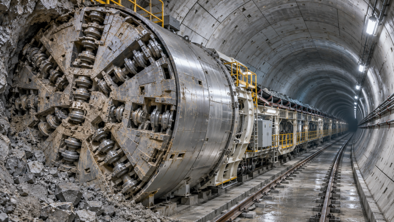
A tunnel boring machine is more than a rotating cutterhead. It is an integrated system that excavates ground, manages the tunnel face, installs support and moves material away from the excavation. Each operation depends on the others: a cutterhead cannot keep advancing indefinitely if the spoil conveyor is blocked, and a lining system cannot do its job if the machine has moved beyond the point where support is needed.
Understanding TBM components gives researchers and project teams a clearer way to interpret machine specifications and tunneling methods. This guide follows the machinery from the cutting face to the backup systems, explaining what the main components do, how they interact and why their configuration changes with the ground.
The Main TBM Components at a Glance
Although designs vary, most tunnel boring machines combine excavation, propulsion, guidance, material removal and support functions. The table below provides a starting point; not every machine uses every component in the same way.
At the Face: Cutterhead, Tools and Drive
The cutterhead is the rotating front assembly that meets the ground. Its design influences how rock is fractured or soil is excavated, how material passes into the machine and how easily cutting tools can be inspected or changed. Openings in the cutterhead allow excavated material to enter the collection area or chamber behind it, but their arrangement depends on the machine’s intended ground conditions.
In hard rock, disc cutters are commonly used to apply concentrated forces that cause the rock to fracture. Their performance depends on factors such as rock properties, cutter condition, thrust and the spacing between cutting paths. Worn or damaged cutters can reduce penetration and increase the loads imposed on other components.
Soft-ground machines may use scrapers, picks or other cutting tools suited to soils and mixed ground. Abrasive sands, cobbles and unexpected boulders can complicate tool selection and wear management. A machine designed for one geological profile may face very different demands when the ground changes along the route.
Behind the cutterhead, the drive system supplies rotation, while the main bearing supports the rotating assembly and transfers loads into the machine structure. Torque and thrust are related but distinct: torque turns the cutterhead; thrust pushes it against the face. Neither figure tells the whole performance story without information about the ground, cutter layout and operating conditions.
How Does a TBM Move and Stay on Course?
Hydraulic thrust cylinders advance the machine, but they need something solid to push against. The reaction arrangement varies by TBM type.
- Gripper TBMs use grippers pressed against the tunnel wall to provide reaction in suitable rock. Thrust cylinders then push the cutterhead assembly forward. After a stroke, the grippers are repositioned for the next advance.
- Shielded TBMs with segmental linings commonly push against the installed lining using thrust cylinders. The force must be managed to avoid damaging the concrete segments.
- Double-shield machines combine features that can allow different operating modes, depending on ground conditions and machine design. They should not be assumed to operate in the same way throughout every drive.
Steering is achieved by adjusting thrust and the orientation of the machine relative to the planned alignment. Guidance systems use surveyed reference information and sensors to indicate the machine’s position and direction. Operators make corrections gradually: a tunnel is not steered like a road vehicle, and the allowable curvature depends on both the machine and the lining design.
This relationship is easy to overlook when reading a specification. A powerful thrust system is useful only if the machine can develop its reaction safely and maintain the required alignment.
Managing the Ground: Shields and Face Support
The shield is the steel structure surrounding much of the front section on a shielded TBM. It supports machine equipment and provides a protected space for operations such as segment installation. Not all TBMs are shielded, however. Open hard-rock machines rely on a different arrangement and may require ground support to be installed as the tunnel advances.
In soft ground, particularly below the groundwater table or beneath sensitive surface assets, controlling the tunnel face is a central part of the design. Two common pressurized machine types approach this task differently.
Earth Pressure Balance Machines
An earth pressure balance, or EPB, machine uses excavated material in a chamber behind the cutterhead to help support the face. A screw conveyor removes material from the chamber, and its operation is coordinated with excavation and advance to help maintain the required pressure.
Soil conditioning agents may be added to modify the excavated material’s behavior. Their purpose is not simply to make soil easier to move: appropriate conditioning can also help create a workable chamber material and support pressure control. The necessary approach depends on the soil and operating conditions.
Slurry Shield Machines
A slurry shield TBM uses pressurized slurry in the excavation chamber to help support the face. The excavated material is transported through a slurry circuit to separation equipment, where solids are removed and suitable fluid can be returned to the machine.
That separation plant is a significant part of the overall system, even though it may sit outside the tunnel. Its capacity and the properties of the excavated material affect how consistently the machine can operate. Choosing between EPB and slurry technology requires a broader assessment of ground behavior, groundwater, environmental constraints and logistics—not just a label such as “sand” or “clay.”
What Happens to Excavated Material?
Once ground passes through the cutterhead, it must travel away from the face. The path differs by machine type. An EPB machine typically discharges material through its screw conveyor onto a belt conveyor or another transport system. A slurry machine pumps a mixture of fluid and excavated solids through pipelines to the separation plant. Hard-rock machines commonly collect broken rock and transfer it to conveyors, rail cars or other haulage equipment.
Removal capacity must match the material being generated, including variations in particle size and water content. If transport or processing falls behind, excavation may need to slow or stop. In a pressurized machine, material extraction also forms part of the face-pressure management process, so changes must be controlled rather than treated as a simple housekeeping issue.
From a project perspective, the spoil system extends beyond the TBM itself. Conveyor routes, pumping distance, separation capacity, storage space and disposal arrangements all influence the practicality of the tunneling method.
Ground Support and Tunnel Lining
Excavating a circular opening is only part of the task. The surrounding ground must remain stable during construction and throughout the tunnel’s intended life. The support method depends on geology, groundwater, tunnel design and the type of machine.
Many shielded TBMs install precast concrete segments to form lining rings behind the cutterhead. A segment erector lifts and positions each piece; the ring is assembled before the machine completes its next advance cycle. Grout is commonly injected into the gap between the outside of the lining and the surrounding ground, with the aim of filling the annular space and limiting unwanted movement.
In suitable rock, an open TBM may instead use support such as rock bolts, mesh, steel ribs or shotcrete, depending on the design and observed conditions. Support installation can affect the excavation cycle, particularly where ground conditions require additional work close to the face.
The lining is therefore not merely a finished surface. It can be part of the machine’s propulsion arrangement, a structural element and a key interface between construction activity and ground behavior.
The Backup Systems Behind the Boring Machine
Behind the main machine is a train of backup equipment that may extend a considerable distance into the completed tunnel. It carries or connects services needed to keep the operation moving: electrical distribution, hydraulic equipment, ventilation, cooling, water, communications, monitoring and material-handling arrangements.
These systems also support the movement of people, tools and consumables. Lining segments, grout materials and replacement cutters must reach the right place at the right time, while excavated material travels in the opposite direction. As the tunnel becomes longer, the logistics chain can become as important to sustained progress as the machine’s cutting capability.
Monitoring links many of these functions. Operators may track parameters such as thrust, torque, penetration, cutterhead speed, chamber pressure and machine position. The value lies in interpreting them together. Rising torque, for example, may prompt investigation, but it does not identify a single cause without the accompanying ground and operating context.
How the Components Work Together During an Advance
Consider a simplified excavation cycle on a shielded TBM using a segmental lining. The installed ring provides a reaction surface for the thrust cylinders. As the cylinders extend, the rotating cutterhead excavates the ground. Material is collected and removed through the machine’s designated transport system. On a pressurized TBM, excavation, advance and extraction are coordinated to maintain the required face conditions.
When the stroke reaches the planned point, excavation and advance are paused as needed for ring building. The erector positions the next set of segments, thrust cylinders are managed to make space for installation, and grouting follows the project’s designed procedure. The cycle then resumes. Actual sequences vary with machine design, operating method and ground conditions, but the dependency is clear: cutting, support, propulsion and logistics cannot be planned in isolation.
For an open gripper TBM, the sequence differs. Grippers provide reaction against the rock, and support may be installed according to the ground conditions encountered. There may be no precast segment ring in the immediate cycle. Comparing the two illustrates why the phrase “TBM components” describes a family of arrangements rather than one universal machine.
Reading a TBM Specification in Context
If you are researching machines for a project or trying to understand a tunneling report, start with the ground and the construction method before comparing headline equipment figures. A useful review asks:
- What ground and groundwater are expected? Rock strength, abrasivity, soil behavior, mixed ground and water pressure all influence machine configuration.
- How is the face supported? Check whether the design is open, shielded, EPB or slurry, and understand the limits and operating assumptions of that choice.
- What provides thrust reaction? Determine whether the machine pushes against grippers, a lining or uses another arrangement, and how that affects the cycle.
- How will tools be inspected and changed? Access requirements and anticipated wear matter, especially in abrasive or variable ground.
- Can support and spoil removal keep pace? Segment supply, grouting, conveyors, slurry treatment and transport routes deserve attention alongside cutterhead power.
- How much variation is expected along the route? A configuration suited to one section may need different procedures or capabilities elsewhere.
A TBM’s performance emerges from the coordination of its components and the conditions in which they operate. Looking at the whole system—from cutting tools at the face to logistics behind the machine—provides a more useful understanding than judging any single specification in isolation.
Have questions about this sector analysis, or seeking best practices specific to your niche? Drop us a line below and let the senior consultants at TF-Strategy assist you.
Related News
 Nov 11, 2026Choosing Equipment Capacity for Different Workloads and ApplicationsExplore equipment application by capacity to match machines to real workloads, reduce bottlenecks and choose cost-effective solutions with confidence.
 Nov 10, 2026Crane Performance Comparison: Load Capacity, Reach and Lifting SpeedCrane performance comparison made practical: evaluate load capacity, reach and lifting speed to choose the right crane for your site and work sequence.
 Nov 09, 2026Heavy Equipment Technology Systems: Telematics, GPS and Machine ControlExplore heavy equipment technology systems, from telematics and GPS to machine control, and learn how to choose the right tools for your fleet and site.
 Nov 10, 2026Selecting a Four-Axle Rear Dump Semi-Trailer for Aggregate HaulingExplore dump special trailers for aggregate hauling. Learn how to compare legal payload, body durability and tipping safety before choosing a four-axle rear dump semi-trailer.
Ms. Elena Rodriguez
Weekly Insights
Stay ahead with our curated technology reports delivered every Monday.