
How Is Cutter Head Fatigue Analysis Used to Predict Service Life and Failure Risk?

How Is Cutter Head Fatigue Analysis Used to Predict Service Life and Failure Risk?
For heavy equipment teams, cutter head fatigue analysis is not just a maintenance topic. It is a practical method for predicting service life and controlling failure risk.
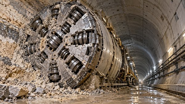
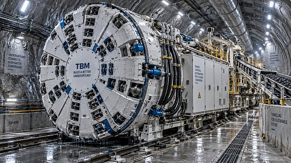
In TBM operations, the cutter head works under repeated impact, vibration, torque fluctuation, and uneven ground resistance. Those loads rarely stay stable for long.
That is why fatigue damage often develops earlier than visible structural failure. A part may look acceptable while cracks are already forming below the surface.
From a technical assessment perspective, cutter head fatigue analysis connects design loads, material behavior, weld quality, and field data. The result is a clearer view of remaining useful life.
It also supports better planning. Replacement windows, inspection intervals, and risk controls become more defensible when they are based on fatigue evidence.
Why Cutter Head Fatigue Analysis Matters in Real Projects
A cutter head is exposed to millions of load cycles during excavation. Each cycle may be small, but cumulative damage is what drives fatigue failure.
The problem becomes more serious in mixed ground, hard rock transitions, fault zones, and abrasive formations. Load variation rises sharply in these conditions.
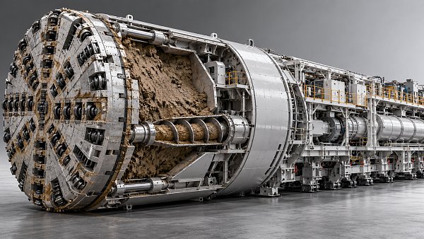
When cutter head fatigue analysis is done well, it helps identify the most vulnerable areas before failure stops production. Typical hotspots include weld toes, openings, stiffener intersections, and cutter mounting zones.
This matters beyond reliability. A cutter head failure can trigger long downtime, costly retrieval work, secondary structural damage, and major schedule disruption.
For organizations tracking total cost of ownership, cutter head fatigue analysis supports earlier and more accurate risk judgment. That directly improves lifecycle planning.
What Cutter Head Fatigue Analysis Actually Examines
At its core, cutter head fatigue analysis studies how repeated stress causes crack initiation and crack growth over time. It is not limited to one single calculation.
A complete evaluation usually combines structural modeling, load spectrum definition, material data, and inspection history. Those inputs need to be consistent with actual operating conditions.
The analysis often focuses on several technical questions:
- Where are the highest cyclic stress concentrations?
- How many damaging load cycles will the structure experience?
- How do weld geometry and fabrication quality affect fatigue strength?
- What is the expected crack initiation period?
- How fast could an existing crack propagate under the recorded load spectrum?
In practice, cutter head fatigue analysis becomes most valuable when it moves from generic assumptions to condition-based assessment. That shift improves prediction quality.
Key Inputs That Shape Service Life Prediction
The accuracy of cutter head fatigue analysis depends heavily on input quality. Weak assumptions produce weak service life estimates, even when the software model looks advanced.
1. Load Spectrum
Fatigue prediction needs realistic cyclic loads. That includes thrust, torque, cutter forces, vibration, bending moments, and transient shock events.
Recent project reviews show that average loads alone are not enough. Peak events and uneven loading often dominate fatigue damage accumulation.
2. Material Properties
Material strength is only part of the story. Cutter head fatigue analysis also needs S-N curves, fracture toughness, hardness behavior, and weld heat-affected zone characteristics.
If the cutter head uses different steel grades or repair welds, local fatigue performance can vary significantly. That difference should not be averaged away.
3. Geometry and Stress Concentration
Openings, attachment points, abrupt thickness changes, and weld terminations can raise local stress. These details often define where cracks begin.
Finite element analysis is commonly used here. It helps translate complex geometry into measurable stress ranges for fatigue evaluation.
4. Operating Environment
Ground variability, water ingress, corrosion, cutter wear, and operator control strategy all influence fatigue behavior. Service life is never determined by design alone.
This is where field intelligence becomes essential. For platforms like TF-Strategy, combining machine behavior with project conditions gives fatigue analysis more strategic value.
How Cutter Head Fatigue Analysis Predicts Failure Risk
Predicting failure risk is not about guessing one final breakdown date. Good cutter head fatigue analysis builds a risk window, not a false point estimate.
That process usually follows a structured path:
- Define actual operating loads and cycle counts.
- Locate critical stress regions through modeling or measurement.
- Apply fatigue design rules or crack growth methods.
- Compare predicted damage with inspection findings.
- Adjust service life estimates as operating conditions evolve.
When crack initiation is the main concern, stress-life methods may be enough. When cracks are already detected, fracture mechanics becomes more useful.
The stronger signal is often trend-based. If measured damage is developing faster than predicted, the failure risk rating should be raised immediately.
This also means fatigue analysis should be updated after major ground changes, cutter replacements, structural repairs, or operating parameter shifts.
Relevant Standards and Evaluation Frameworks
For technical and standard-driven work, cutter head fatigue analysis should align with recognized fatigue assessment practices. The exact framework depends on design code and project requirements.
Common references may include welded structure fatigue guidance, finite element verification rules, fracture assessment procedures, and material qualification standards.
In engineering reviews, the following checkpoints are usually important:
- Whether the load case envelope reflects real excavation conditions.
- Whether weld classes and detail categories are correctly assigned.
- Whether inspection intervals match predicted crack growth rates.
- Whether repair history has been included in the fatigue model.
A standards-based approach makes cutter head fatigue analysis more credible. It also gives procurement, engineering, and operations teams a shared decision language.
Common Mistakes That Distort the Analysis
One common mistake is using static design loads to represent cyclic excavation behavior. That shortcut usually understates fatigue damage.
Another issue is ignoring fabrication details. In many failures, weld profile quality and local residual stress matter more than nominal plate strength.
Some evaluations also treat the cutter head as a fully uniform structure. In reality, repairs, wear, and local reinforcement can create very uneven fatigue response.
There is also a timing problem. If cutter head fatigue analysis is only performed after visible cracking, the options are already narrower and more expensive.
How to Turn Analysis into Action
The best value of cutter head fatigue analysis appears when results drive operating decisions. A report alone does not reduce failure risk.
A practical action plan usually includes:
- Set inspection points around the highest fatigue hot spots.
- Link inspection timing to operating hours and geological transitions.
- Define crack acceptance limits and escalation thresholds.
- Use repair methods that preserve long-term fatigue strength.
- Update the model after each major intervention or abnormal event.
This is especially important in large infrastructure projects, where a single cutter head event can affect commercial delivery, safety performance, and contract exposure.
Viewed this way, cutter head fatigue analysis is not just an engineering calculation. It is a decision tool for balancing reliability, cost, and operational continuity.
Conclusion
Cutter head fatigue analysis helps predict service life by turning cyclic loads, material behavior, and structural detail into measurable failure risk.
It works best when supported by realistic load data, code-based assessment, and disciplined field inspection. That combination makes early damage visible before it becomes disruptive.
For organizations working across TBM and other heavy equipment sectors, the wider lesson is clear. Better fatigue intelligence leads to better timing, lower uncertainty, and stronger engineering decisions.
The next practical step is straightforward: review current cutter head fatigue analysis methods against actual field loads, repair history, and inspection evidence, then close the gaps that still rely on assumption.
Related News
 Oct 23, 2026Selecting Lifting Equipment for Nuclear Component Transport: Key Safety CriteriaSelecting lifting machinery for nuclear component transport? Discover essential safety criteria, load control checks, and supplier requirements to guide confident procurement.
 Oct 22, 2026Tunnel Boring Machines in Southeast Asia: EPB vs. Slurry for Soft GroundCompare tunnel boring machines Southeast Asia projects rely on: EPB vs. slurry for soft ground. Discover how groundwater, settlement risks, and spoil handling shape the right choice.
 Oct 21, 2026Choosing Tunneling Equipment for the Middle East: Rock, Soil, and GroundwaterCompare underground tunneling equipment Middle East projects need. Explore rock, soil, groundwater, and TBM options to reduce risk and make confident procurement decisions.
 Oct 20, 2026Which Heavy Machinery Maintenance Standards Apply to Your Construction Fleet?Discover which heavy machinery maintenance standards apply to your fleet. Clarify legal duties, OEM requirements, and inspection rules to reduce risk and keep equipment ready for work.
Related News


Geological Boring Fellow
Weekly Insights
Stay ahead with our curated technology reports delivered every Monday.